Since you didn't say RK70 or it's J suffix, can only presume BASIC so here goes...
Your Turner Mic;
Has a 4 POLE - DOUBLE THROW switch - spring loaded plunger.
Three of these Poles are used, One for Audio Out and SPECIAL CONDITION,
One uses 3 Traces for Common mode Switching RX to TX with Common - but is NOT GROUNDED.
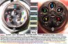
The Mic leaves you access and has 4 "holes" or traces -
Trace 1 = Audio
Trace 2 = Transmit
Trace 3 = Common
Trace 4 = Receive
HOWEVER, your Grant XL or Cobra 148GTL - use 5 wires.
BOARD ground on Radio is SEPARATE from Shield (Audio) Ground - Treat this accordingly.
Traces 2, 3 and 4 - don't need anything special - Radio provides the "RETURN PATH" for grounding the SWITCHING mode - Receive to Transmit.
Due to this Mics' sensitivity and Ground / Shielding requirements - SOLDER SHIELD of Mic Cord to LOCATION 2 in diagram. It is the Battery Negative Terminal - also your Audio Common - you'll need that for the Grant / Cobra 5-pin radio.
So Grant - Cobra is as Follows...
Pin 1 - Audio
Pin 2 - SHIELD
Pin 3 - Speaker Ground (Uses Common Switching AT Radio)
Pin 4 - COMMON SWITCHING
Pin 5 - Transmit
Audio wire is your wire wrapped in Shield - ok? - Goes to - Pin 1 on Mic Plug!

See attached for review...