The Yaesu FT-2700RH 2m/440 dual-band transceiver comes configured with 70 cm front-panel-selectable step sizes of either 12.5 kHz or 25 kHz. The transceiver is unable to key up repeaters on frequencies "in between" those intervals. (E.G., you can dial in 450.0000, 449.9875 and 449.9750, but not the repeater frequency I needed, viz., 449.980.) If I tried to use the closest frequency to the one I needed, the audio was a little distorted and, worse, I could not key the repeater. The ideal would be to modify the radio to have a 5 kHz step size.
A brief article appearing in mods.dk from 1998, with no author identified, showed a table of values for D13, D14 and D15. With no explanation, these were initially assumed to be DIP switch values. After being unable to locate any DIP switches in the radio, it was determined that these "D's" were diodes, instead. Here is an excerpt from that table:
D13 D14 D15
0 0 0 --NO WORK
0 0 1 --430-440 MHZ 12/25
0 1 0 --430-450 MHZ 12/25
0 1 1 --430-440 MHZ 5/10
1 0 0 --*NORMAL* AS SHIPPED
1 0 1 --430-440 MHZ 12/25
1 1 0 --430-440 MHZ 12/25
1 1 1 --430-450 MHZ 5/10
The "NORMAL AS SHIPPED" (1/0/0 configuration) was assumed to represent the configuration, viz., 440-450 MHz with 12.5 or 25 kHz frequency spacing. Since I needed that same frequency range covered, but with smaller step sizes, the closest configuration to the one I needed was the last one in the table, configuration 1/1/1. I didn't need the wider frequency range, but the exact option I needed was not represented in the table, viz., 440-450 MHz and 5/10 kHz step size. So, configuration 1/1/1 would have to be the choice.
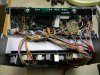
The diodes were located on the control board under the "floating" optional tone board visible in the first image below.
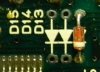
As you can see from the close-up in the next figure, there is a diode only in position D13, corresponding to the NORMAL AS SHIPPED entry in the table.
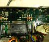
These diodes (D13, D14, D15) are shown on the control unit schematic but the 1Nxxx part number is not indicated. I chose to use a commonly available diode, 1N914. This application is not part-type critical. The two additional diodes were soldered into positions D14 and D15. It was difficult to remove the control unit board from the radio, so the diodes were "tack-soldered" onto the front side of the board, as shown.
After completing the modification, the frequency step sizes on the 70 cm band are 5 and 10 kHz, instead of the 12.5 and 25 kHz. Although not needed, the frequency range has also been increased to 430 - 450 MHz from the previous 440 - 450 MHz.
Caveat: We did not attempt to confirm the complete accuracy of the table above. (It seems odd that three of the table configurations all show the same result; viz., 0/0/1, 1/0/1 and 1/1/0 all show 430-440 with 12/25.) However, one can now attest that at least the last (1/1/1) configuration entry is correct. In making other modifications based on this table, one should proceed with due caution.
73
Jeff
A brief article appearing in mods.dk from 1998, with no author identified, showed a table of values for D13, D14 and D15. With no explanation, these were initially assumed to be DIP switch values. After being unable to locate any DIP switches in the radio, it was determined that these "D's" were diodes, instead. Here is an excerpt from that table:
D13 D14 D15
0 0 0 --NO WORK
0 0 1 --430-440 MHZ 12/25
0 1 0 --430-450 MHZ 12/25
0 1 1 --430-440 MHZ 5/10
1 0 0 --*NORMAL* AS SHIPPED
1 0 1 --430-440 MHZ 12/25
1 1 0 --430-440 MHZ 12/25
1 1 1 --430-450 MHZ 5/10
The "NORMAL AS SHIPPED" (1/0/0 configuration) was assumed to represent the configuration, viz., 440-450 MHz with 12.5 or 25 kHz frequency spacing. Since I needed that same frequency range covered, but with smaller step sizes, the closest configuration to the one I needed was the last one in the table, configuration 1/1/1. I didn't need the wider frequency range, but the exact option I needed was not represented in the table, viz., 440-450 MHz and 5/10 kHz step size. So, configuration 1/1/1 would have to be the choice.
The diodes were located on the control board under the "floating" optional tone board visible in the first image below.
As you can see from the close-up in the next figure, there is a diode only in position D13, corresponding to the NORMAL AS SHIPPED entry in the table.
These diodes (D13, D14, D15) are shown on the control unit schematic but the 1Nxxx part number is not indicated. I chose to use a commonly available diode, 1N914. This application is not part-type critical. The two additional diodes were soldered into positions D14 and D15. It was difficult to remove the control unit board from the radio, so the diodes were "tack-soldered" onto the front side of the board, as shown.
After completing the modification, the frequency step sizes on the 70 cm band are 5 and 10 kHz, instead of the 12.5 and 25 kHz. Although not needed, the frequency range has also been increased to 430 - 450 MHz from the previous 440 - 450 MHz.
Caveat: We did not attempt to confirm the complete accuracy of the table above. (It seems odd that three of the table configurations all show the same result; viz., 0/0/1, 1/0/1 and 1/1/0 all show 430-440 with 12/25.) However, one can now attest that at least the last (1/1/1) configuration entry is correct. In making other modifications based on this table, one should proceed with due caution.
73
Jeff