• You can now help support WorldwideDX when you shop on Amazon at no additional cost to you! Simply follow this Shop on Amazon link first and a portion of any purchase is sent to WorldwideDX to help with site costs.

Ramsey PR40 440Mhz Preamp kit

Moleculo

Ham Radio Nerd
Apr 14, 2002
9,194
1,674
283
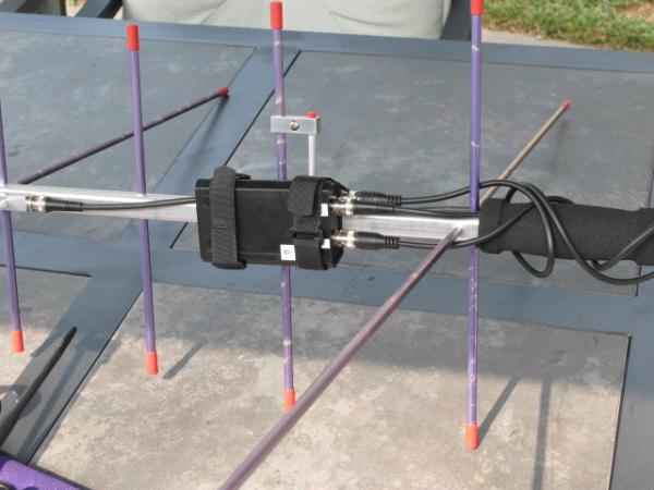
I decided to look for a 440Mhz preamp to use with my handheld 2m/440 Arrow satellite yagi. After some sticker shock at the prices of factory devices, I started looking for some kits. Since this preamp won't be inline while transmitting, I didn't need to worry about bypassing it while TX'ing.

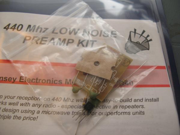
That's when I came across the Ramsey 440 Mhz Preamp kit for $15. They also have 2m and 220mhz kits. It only comes with the preamp circuit - no box, RF connectors, and no switches. You can get it here:
PR10, PR20, PR40 - 2 Meter, 220 MHz, 440 MHz Preamps - Ramsey Electronics

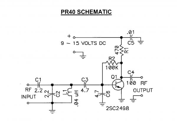
I got the kit today and boy is it simple. This thing is really only a couple dollars of parts. You can download the instructions from Ramsey's website, but they omit the schematic. I'll scan the included schematic and upload it here so others can build it on their own.

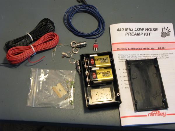
Here's a quick pic of the contents of the kit:

582-1247710281-b14e47f2a3a36dd0b2e4b2d921309554.jpg


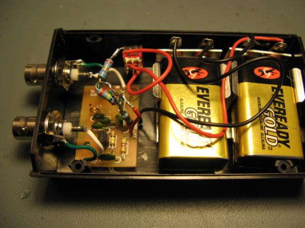
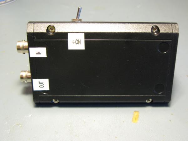
I still need to pick up a project box, some BNC connectors, some super small coax, and a switch to bypass and turn off the amp. This kit runs on 9-16VDC. The manual says you'll get about 20db gain and I'm assuming that's at it's max voltage. So when I figure out how to power it, I'll either try to find some higher voltage batteries, or use two 9V batteries in series with a simple voltage divider circuit.
 

I finally located the remaining parts and had time to assemble the amp. Believe it or not, I couldn't find BNC bulkhead connector anywhere until I went to the electronics swap meet.

First, here is the schematic of the Ramsey preamp:

638-1250444120-a6644b0e16288aeac594e47adf11c77c.jpg


Here are all of the parts laid with the batteries & board sitting in the box to determine fit. this project box had the mounting posts right in the middle of the box, so I had to use a dremel tool to cut them off to make enough room for everything.

632-1250443904-5d6e3d986f3e1b245ed5487f9db47629.jpg


First up, drill the holes and mount the BNC connectors and switch:

633-1250443904-713ca3be3bd6a18ed076c65dea70b9b5.jpg


Ramsey PR40 Kit assembled:

634-1250443904-848d7dd95bc52b6cb922e3c5921eb4d3.jpg


Everything installed in box and ready to go:

635-1250443904-3705410122a73bb1dae18bf77e2340b5.jpg


The batteries are hookup up in serial to produce 18V at full charge. Parts of the manual say the kit is "rated" for up to 16v, the schematic says 15v. You can see in the above picture some 1/2 watt resistors inline on the power feed. This was an attempt at making a simple voltage divider to drop the 18v down a little. That didn't end up working out so I removed it. I'm not really all the concerned about 2 volts more...as the batteries weaken the voltage will drop anyway.

I was also going to use the small coax in the original picture for the RF leads, but the coax was too stiff and as you can see the RF leads are barely an inch long anyway.

Here is the box all buttoned up:

636-1250443904-a371209b32db0e3f71b6b04539b0fd3f.jpg


Keep in mind that with the preamp in this configuration you cannot transmit on 440Mhz while the amp is inline. If you want to do that you need to rig up a RX bypass. You could do it with a RF sensing transistor and relay or some other method. Ramsey even has another little kit you could purchase (RFS-1) to do this. I'm not concerned with this issue since I'm using a duplexer on the antenna to RX only 440mhz and TX on 2m.

And finally, here is the preamp attached to the Arrow 2m/440 antenna:

637-1250443904-3b0ae72452420dc29e7fe3e32daa0eca.jpg


The only extra cable with BNC ends I had laying around was longer than necessary, so I wrapped the excess around the handles until I can pick up a shorter one.

Initial test results were fantastic! I pointed the Yagi south toward a repeater that is over some hills, about an hour drive away from me. With my HT attached and the 7 element yagi, it was just breaking the squelch and the conversation was barely intelligable. When I flipped on the preamp, it brought the signal up to an S5, 100% perfect copy, barely any noticeable noise on the HT. I then put the preamp inline with a little 1/4 wave 440 magmount that I have in the house on a piece of steel and found another active repeater. I turned on the attenuator on the HT to drop the signal to an S5. When I flipped on the preamp, the signal came up to S9.

Total cost for the kit and all parts (not including batteries): about $35.

Next up, testing out on some satellites.
 
I don't suppose you figured out a fail safe configuration for this particular warning in the manual?
Under no circumstances should transmitter RF ever be applied to the input or output of this preamplifier. Even though this sounds like unneeded advice and common-sense knowledge, we should remember that most of today’s receivers are in transceiver configuration, and that all it takes is one accidental push of a button out of habit, or an inadvertent bump of a keyer, to destroy a preamplifier.
I ask because in the heat of the moment while squirting birds, it is really really easy to not notice the B circuit on the VX-8R is enabled when A is configured for 2M transmit and B is configured for 70cm receive. I've done it a couple of times, and the caution in the manual suggests I'll fry the preamp.

?? A diode on the OUT feed to prevent accidental feed in through the OUT? :confused:

...Tom W3ROK

P.S.: Yes, I'm going to try this little kit. I found commercial versions that run nearly $300 MSRP, so for $30 or $40 total, this is well worth trying. Looking forward to hearing if you replaced your voltage splitter solution with a diode or two and how well that worked to reduce current.
 
I haven't worried about it yet, but if I did, I probably would just put a simple PIN Diode circuit on the output. That seems like the simplest solution, but I would probably need someone to help me with the proper circuit design.

One way to solve your problem (what I did) is to program in the satellite frequencies as memories in an odd split configuration and only use one VFO. Since the VX-8 does not have full duplex capability between VFO's, you're not accomplishing much by using both VFO's on the satellite. For each bird, I programmed in 5 consecutive memories with the RX frequency varying to account for doppler shift. The TX frequency stayed the same. This way, when you key the radio always automatically changes to the 2m side. On the Alinco DJ-G7 radio, it does have full duplex capability, but it can only TX on the A VFO. You can use one of the duplex memories on that radio to accomplish the same thing.
 
Looking forward to hearing if you replaced your voltage splitter solution with a diode or two and how well that worked to reduce current.

I haven't done that yet. It seems to work fine at 18v and I want to see how rapidly it eats the batteries and drops the voltage down anyway. If I end up popping the transistor, it's only a .50 cent part so no big deal to replace it and add a couple of diodes on the power feed.
 
I haven't done that yet. It seems to work fine at 18v and I want to see how rapidly it eats the batteries and drops the voltage down anyway. If I end up popping the transistor, it's only a .50 cent part so no big deal to replace it and add a couple of diodes on the power feed.


That transistor specs a max voltage of 20 volts so running battery power as opposed to a wall wart with God knows what voltage you should be OK. At least there are no spikes with batteries. (y)
 
Any idea on the bandwidth of this?

From the manual:
"L1 and C2 form a tuned input filter for the preamp to reject out-of-band signals. The 3 db bandwidth of this filter is 24MHz. L1 is adjustable for peak performance."

And now for something funny:

Check out this old post about this preamp kit on amsat.org's old BBS. Look at the name of the poster and then go look up my callsign. What are the chances.... :unsure:

Ramsey PR40 70cm preamp kit
 
I read your posting with much interest because I put together the same kit and struggling to make it work. The parts placement and soldering quality have been carefully checked many, many times, no issue there.

Ironically the effect I am getting with this kit inline is quite opposite to what I would expect from a preamp -- it attenuates the 440 Mhz band making strong S9 signals S3 and turning weak signals into hiss noise. I tried different power options (batteries, voltage regulators, etc) to no avail. I also tried replacing C2 with a trimmer 2-10pf hoping this would allow me to tune LC bandpass filter better. Again, nothing. Tried different antennas, etc...

My Vbe voltage reads +5.11V with +14V supplied and I suspect that this Vbe is rather high. Vce is around +11V. I was wondering, if it is not a big hassle, if it might be possible for you to check your Vbe and Vce voltage on your working kit and post it into the thread. I'd really appreciate it.

Thanks!
A1000
 
My Vbe voltage reads +5.11V with +14V supplied and I suspect that this Vbe is rather high. Vce is around +11V. I was wondering, if it is not a big hassle, if it might be possible for you to check your Vbe and Vce voltage on your working kit and post it into the thread. I'd really appreciate it.

Yep, no problem. Vbe = 0.76, Vce = 9.9v with 15.5v supplied. I wonder if you got R1 & R2 reversed, or if they're just the wrong value in the kit? I'm no electronics circuit genious (as you can tell from some of my posts) but your Vbe reading is waaaaay to high to properly bias that transistor.
 
One quick comment...it didn't take all that long to drop it down to under 16v...especially if you accidentally leave it on over night...
 
Thanks for checking those voltages. Yeah, I am not sure why my Vbe is so high. The resistors are of correct value R1=470 Ohm and R2=97K (I do not think +/- 3K would matter on 100K resistor) and placed correctly on the board. The transistor in the kit is C2570, placed correctly. No shorts, no opens. Oh well... :headbang
 
I worked AO-51 tonight with the preamp inline. This was a 41 degree pass for me. One thing I noticed this evening is that with the preamp on I started picking up the satellite almost immediately on the horizon. In the past, I was never able to do this...I didn't start picking it up until it had some elevation on my location. I switched the preamp off and on a few times to verify and was really pleased at the difference it made. I could hear it through it's entire pass.
 
I worked AO-51 tonight with the preamp inline.
I worked AO-51 tonight, too. Preamp kit is in the mail. Did you pick up your project box and 9V battery clips locally, or do you have a secret source ;)

...Tom
 
I got the project box and battery clips at Fry's Electronics. The box had mounting posts (for screws) that were in all the wrong places, so i had to use a dremel tool to cut them out. I saw some project boxes at the electronics swap that would have worked better. The main board is just hot glued to the project box. I was a little hesitant about doing it this way, but it seems to be working out OK. At least that way if I have to pull it back out to replace something, it won't be too difficult to lift off the box. The battery clips are velcro'd to the board. I did it that way because the clips are REALLY strong and it can be tricky to get batteries in and out of in that small space. By making the battery leads a little longer and mounting them with velcro, I can lift them out and use two hands to do it. It seems to be working.

BTW, did I work you? I don't have a voice recorder so I'm not even trying to keep a log.
 

dxChat
Help Users
  • No one is chatting at the moment.
  • dxBot:
    Tucker442 has left the room.
  • @ BJ radionut:
    LIVE 10:00 AM EST :cool:
  • @ Charles Edwards:
    I'm looking for factory settings 1 through 59 for a AT 5555 n2 or AT500 M2 I only wrote down half the values feel like a idiot I need help will be appreciated