• You can now help support WorldwideDX when you shop on Amazon at no additional cost to you! Simply follow this Shop on Amazon link first and a portion of any purchase is sent to WorldwideDX to help with site costs.

Construction of 140W PEP EB63 amplifier + Low-Pass Filters

eagle1911

Active Member
Jan 21, 2011
327
20
28
here's my newest acquisition:

AmpKitweb.jpg


A complete set of parts for the EB63 amplifier (2xMRF454 class AB), which is rated for 140W PEP output. I got it for a song ($60) on ebay.. plus as a bonus it included 2 Communications Concepts low-pass kits for 20 and 40m. Not a complete set, but way better than nothing. I can get the rest easily enough here.. I just need to get a heatsink and have it drilled for the transistors and temp diode (this might be available from comm. concepts, not sure yet).

My plan for the LPF set is to do another free-standing filter unit like my previous LPF project, using the LPF board kits pictured above plus 6 of these (or something similar if I can find it cheaper).. I'm lazy sometimes and buy modular components. A DPDT 6-position switch will control the relays.

Over the coming weeks I'll be documenting the build here.. should be a great learning experience and a lot of fun!
 
  • Like
Reactions: 1 person

I got a lot more done tonight than I had planned. The board is complete except that the MRF454s are just sitting on the board for the photo. They won't be soldered in until the board is mounted on a heatsink.

Amp1web.jpg


For detailed info on the construction process see here.

LPFs are next!
 
I suspect you just placed the MRF-454 transistors on the board in any direction just to take the picture and the instructions will show the correct orientation. If not, you should be aware they are on the board in the reverse position and this will burn them open on power up. The cut tab is the collector and should face the larger output transformer. Good luck with the project.
 
^Good eye!! I totally missed that.. You are correct, they're posing for the picture only. Plus it was around 1:30AM when I took that pic. I was a little tired lol..
 
Actually, I've been looking at the Flex 1500. I think I'm going to try the SDR route.. I've been using a friend's 817, and I like it, but the software defined stuff fascinates me.
 
Update!

Things are coming along nicely.. I've added feedback to the amplifier, as the EB63 has none by design. This consists of a .01uF capacitor, 47 ohm 5W resistor and a 20uH vk200 choke on each transistor. This is untested, but should work..

I've got filters finished for 160-40m and 10m. Still working on 20 and 15. I've got a project box lined up, and I just received a length of RG-174 coax for the internal wiring of the low-pass filter set. I've decided to wire things up directly to a 2-pole 6-position switch, which eliminates the need for relays and therefore external power.

I'll be posting more details on the construction of the filters shortly.

amp-filters.jpg
 
Eagle, check the connection on your 47 ohm 5 watt negative feedback resistors. It looks like you have the bottom end of these resistors tied to ground. This end should connect to the base terminal on the output transistors and not ground. Other then this possible error, your work looks good.
 
This is an awesome build thread with great pics and helpful feedback from other members. I love it! (y)
 
@Shockwave: Actually that's just an anomaly of the photo. The ends of the resistors connect to the little choke coils you can see there, the other end of which is soldered to the base of each transistor. The connection at the choke is actually about 1/4" off the board surface, but it looks like it's right on it due to the lack of depth in the picture Thanks for your input though.. it is highly valued!

@Moleculo: It's proving to be a fun project! I can't wait to get it on the air..
 
Last edited:
@Shockwave: Actually that's just an anomaly of the photo. The ends of the resistors connect to the little choke coils you can see there, the other end of which is soldered to the base of each transistor. The connection at the choke is actually about 1/4" off the board surface, but it looks like it's right on it due to the lack of depth in the picture Thanks for your input though.. it is highly valued!

@Moleculo: It's proving to be a fun project! I can't wait to get it on the air..

No problem. I hadn't considered that possibility and just wanted to make sure you get the full advantage of your time and work into the project.
 
You and Bob85 and others helped me with figuring this stuff out initially through your posts, so for that I'll always be grateful. I'm no stranger to electronics, but until now I've worked exclusively with digital and AF analog stuff. RF is a whole different ballgame, even more so the higher you get in frequency. These kits are a learning experience involving skills that I'm planning on using to design and build my own amps eventually. The component supplies are growing and the books are piling up. I've got a couple state of the art MOSFETs from Freescale capable of over 1kW CW from 1.8-150MHz in a single push-pull package (MRF6VP11KH). In the near future my plan is to try to build a 500-700W PEP class AB amp with one of them. They're not necessarily designed for SSB usage, but they are classified as AB.
 
More stuff:

First off, let me post a couple things that I should have posted right off the bat since I can't edit the OP anymore.

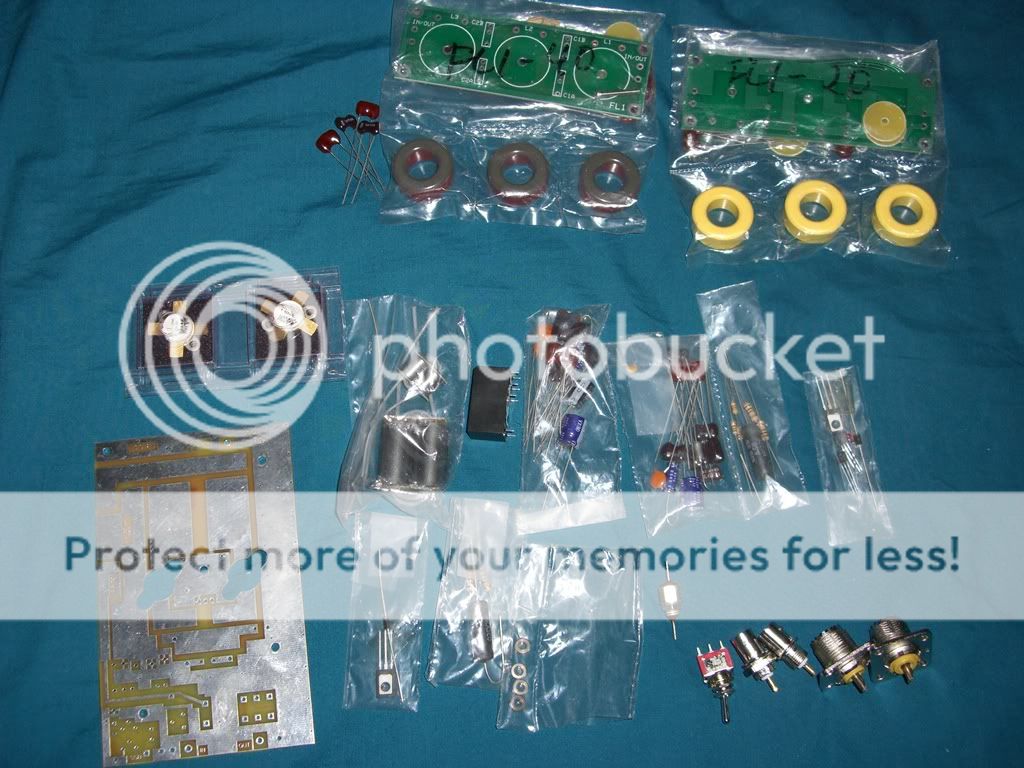
The complete kit for the EB63a amplifier and all 6 filters can be purchased quite reasonably from Communication Concepts, the amp here and the filters here. This is just in case anyone else wants to try their hand at building one of these kits.

It's absolutely worth browsing their other products. they have several amplifier kits to choose from, most of which are better than the EB63. The pricing of their kits isn't bad either..

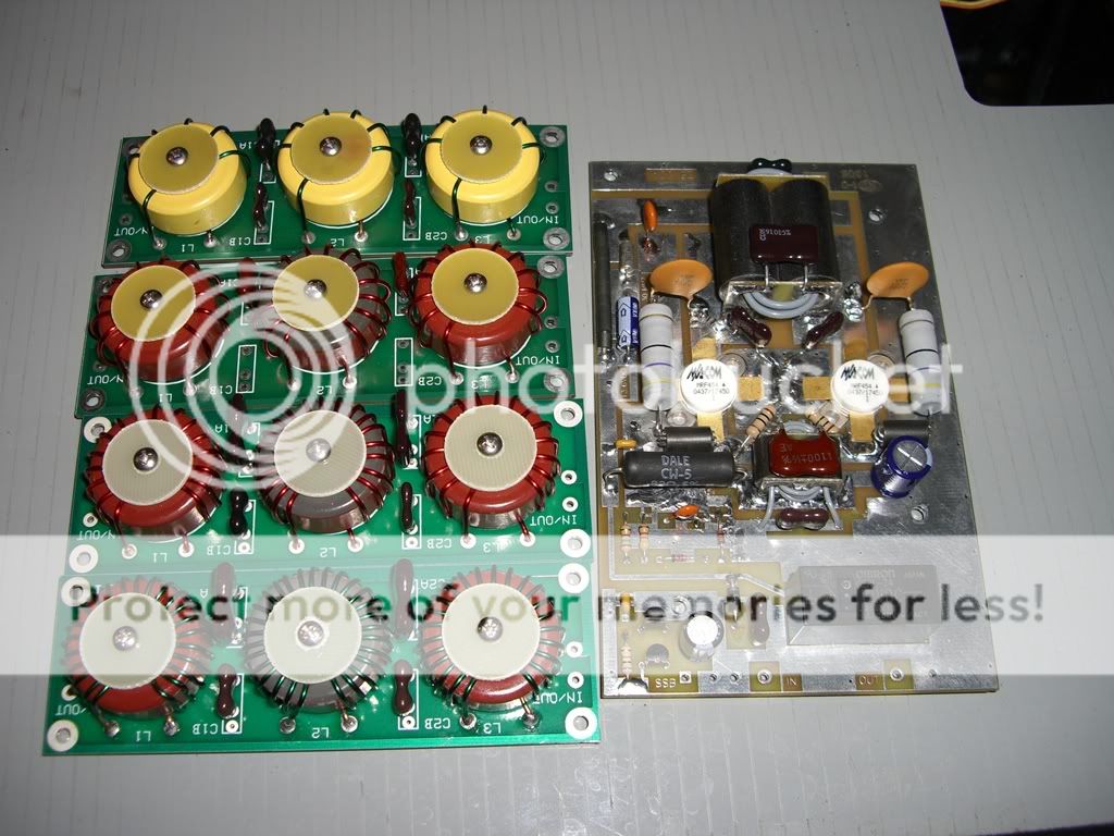
Regarding the filters:

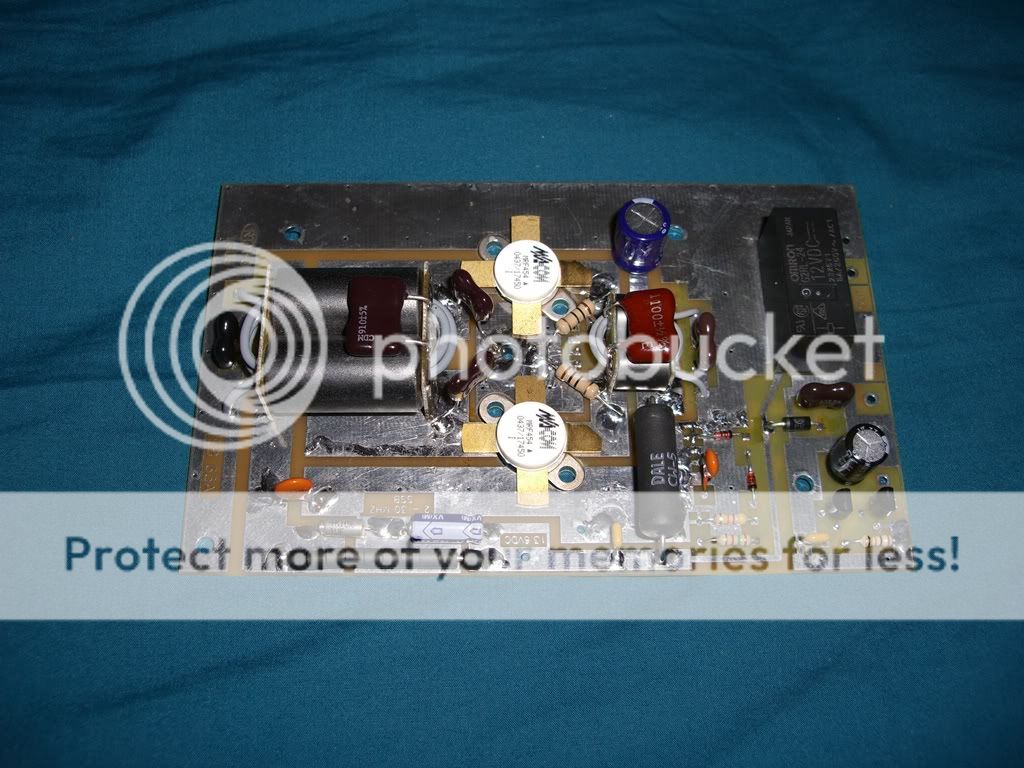
I'm laying out a bit of information about the low-pass filters (LPFs) because they are an important part of a solid-state amplifier setup, either mounted inside the amp or built as an external band-selectable accessory. There is also generally a lot more info to be found on building amplifiers than building filters, especially in the CB world.

LPFs are important because they help remove unwanted harmonic junk from an amplified signal, which helps keep noise down across the radio spectrum. This helps all radio operators in obvious ways. They are also a component that's not often found in CB-type solid-state amplifiers (although some manufacturers include them), which is unfortunate since they aren't really very hard to design or build, especially with the software available today.

ELSIE filter design software and information for designing custom filters from scratch:


The filters I've used here are a kit, but for those interested in using software to design your own filters specific to your application, ELSIE works really well. It's simple, free and very easy to use. For most 2+ transistor RF amplifier applications, a simple 5 pole Chebyshev filter either capacitor-input or inductor-input can be used. This information can be entered directly into Elsie, along with a Ripple Bandwidth of XXMhz (can be any number depending on the band to be used, for CB it would be 27), an Order (N)[7max] of 5 and an Input Term of 50 (for 50 ohm impedance to match the amplifier and transmission line). Bold words above are the actual functions in the ELSIE software, and you can see exactly where to enter them in the first screen of the program after you select "New Design" from the opening menu. Input the above figures and hit the "schematic" button at the top of the screen and BAM!, you've got a filter schematic ready to be built. To find what cores are best for your application, consult toroids.info. Once you've got a core picked out, you can usually just enter the part number on ebay and find them. You select toroid cores based on your frequency of operation and your power handling requirement. For the shorter wavelength bands (20m and up) air core coils can be made simply by winding heavy-gauge magnet wire around a cylindrical form. Owning an L/C (inductance/capacitance) meter is a must when hand-winding cores for a custom design, but they can be had fairly cheaply on ebay or Amazon.

Here's a little more info on building the filters:

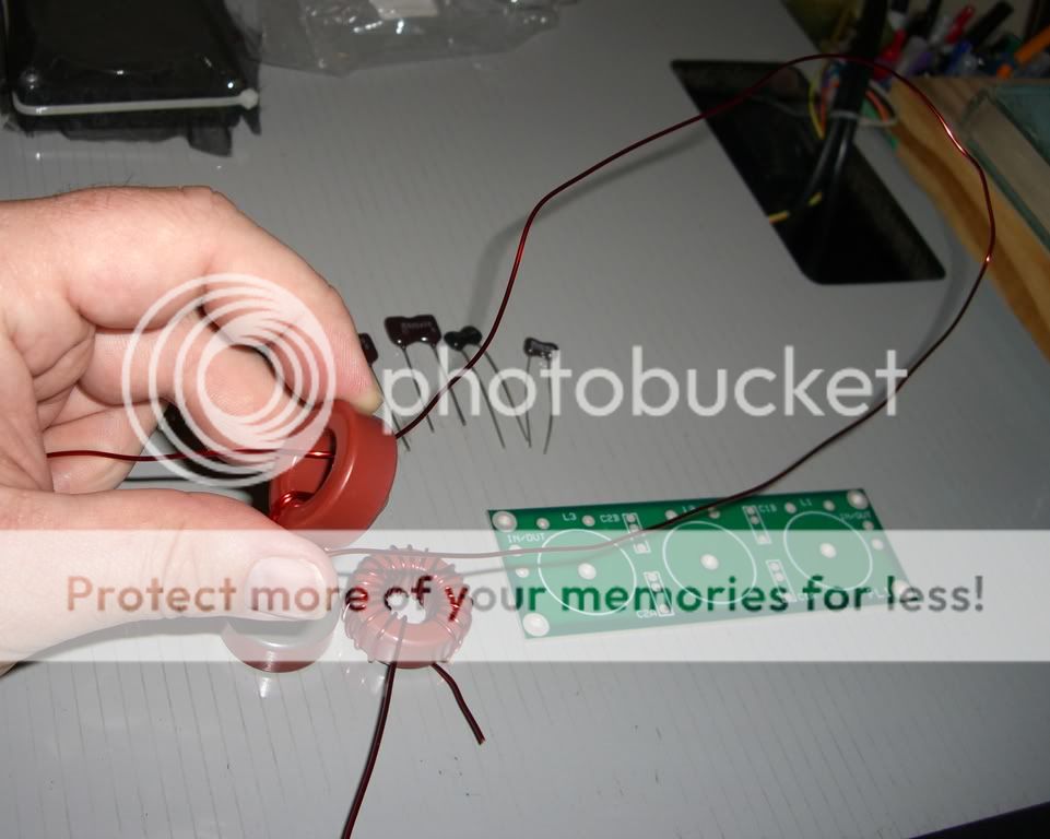
The toughest part about building the filters is winding the toroids.. particularly for the longer wavelength bands. I started with 160m since it involved the most turns of wire around the ferrite toroid core, namely 28 turns on the middle coil and 23 turns on the outer coils. The pics I've posted here were taken while building the 80m coil, which required 20 turns on the middle coil and 16 turns on the outer coils.

A helpful guide on how to wind toroids can be found
here.

Basically It's just like you would think. You just pass the wire through the toroid core over and over, pressing the wire against the core with each turn so it's snug against it. Most coils are wound clockwise if it's not stated otherwise. To make sure you're winding clockwise, start by holding the toroid with the hole facing you. Take the wire and pass it through the hole from the back so that it passes through the hole towards you. Pull the wire through almost to the end, with a couple inches left over. Hold the wire tightly and wrap it down and around the core, passing again through the core to the right of the first pass. Holding the core so that the hole is facing you, then winding to the right after passing the wire through the core from the back ensures the the wire is wound in a clockwise direction. To verify this, you can compare the first few turns to the pictures here to see that the leads are on the same side of the coil.. these coils are all wound clockwise. A counter-clockwise coil will end up with the leads on opposite sides. The direction doesn't make a difference in the value of the coil, but it does ensure that your coils can all be mounted the exact same way. Once the coils are wound, you must strip the enamel insulation off the leads (I use an x-acto knife to scrape it off) and tin the leads with solder to ensure the best connection once it's soldered into a circuit. RF can be very senstive to bad connections.
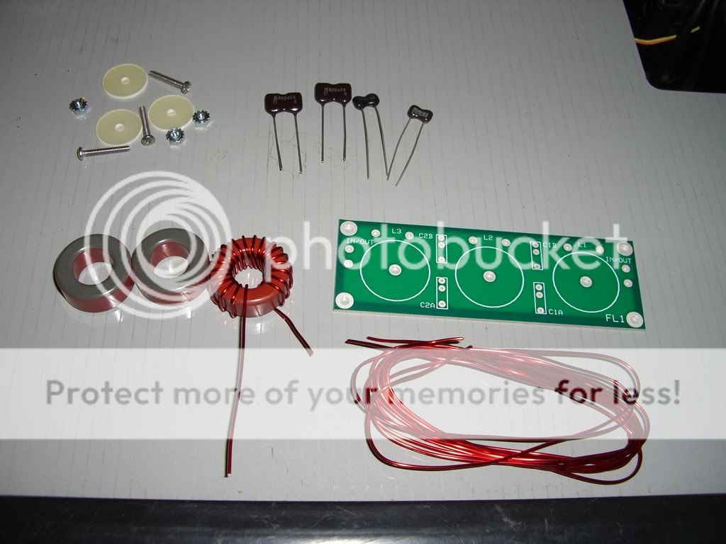
Capacitors:

The capacitors are typically dipped silver-mica or ceramic disc, with silver-mica being preferred due to stability. The values provided by design software do not always match up to a manufactured capacitor, so often multiple capactors are used in parallel to achieve special values. Parallel capacitors add up directly in terms of value.

here's a few pics of the build process:

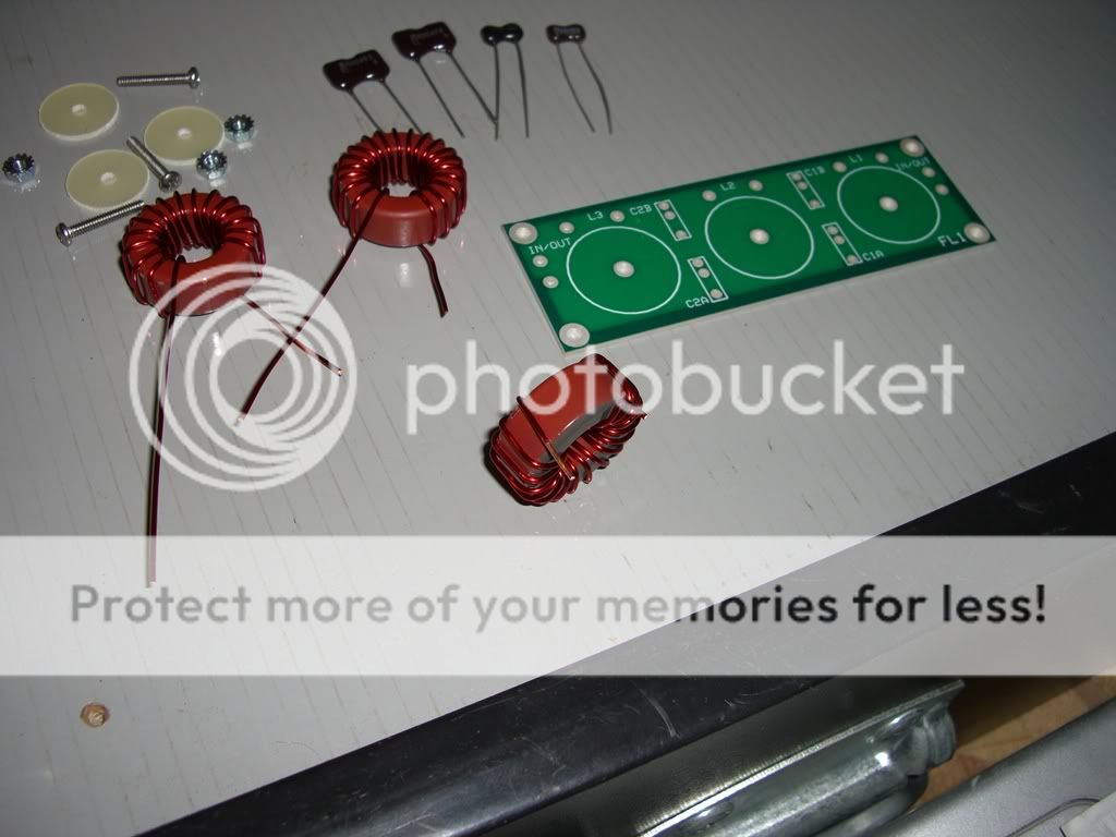
This shows all the parts for the 80m filter kit:

filter1web2.jpg


Winding the toroids:

filter1web.jpg


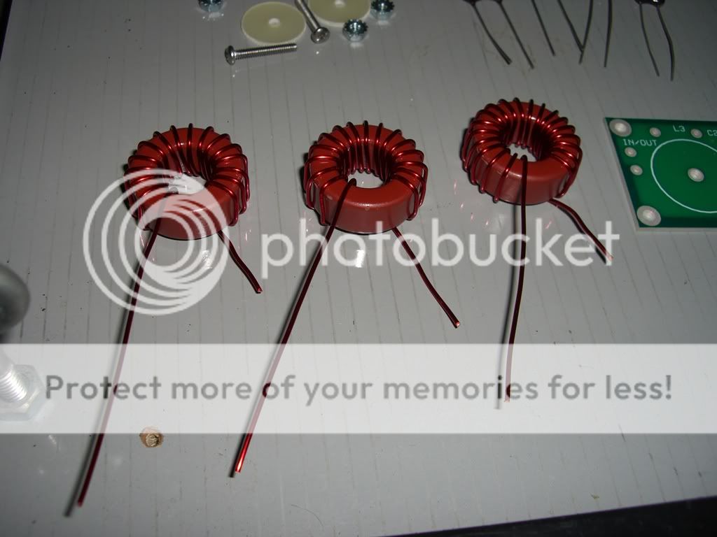
Fully wound toroids (can be used as reference for clockwise windings):

coilsweb1.jpg


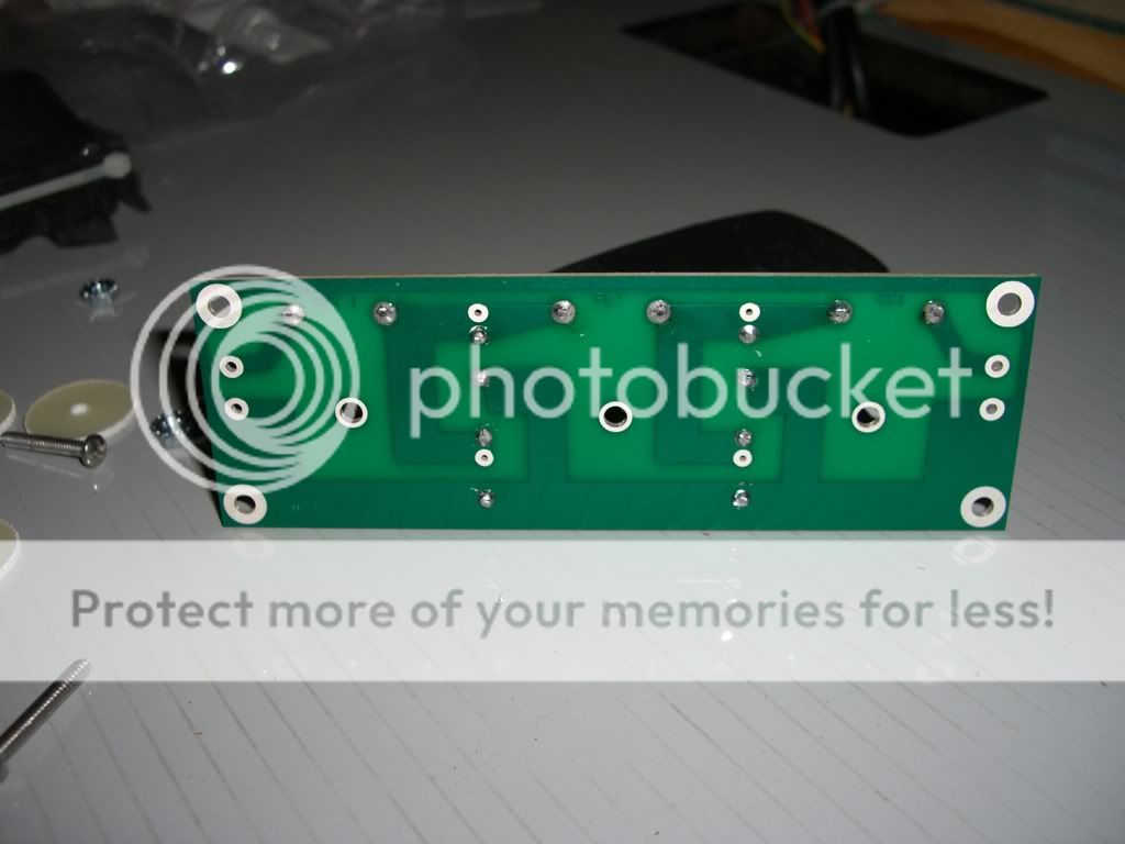
Toroid with leads cut and positioned to fit the PCB:

coilsweb2.jpg


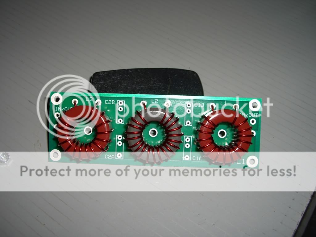
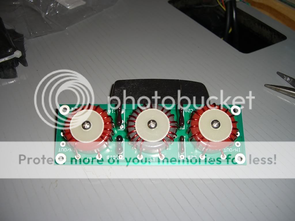
Toroids soldered in place:

coilsmounted1.jpg


Back of board (to show circuit):

filter1webback.jpg


All Done!

filterdoneweb.jpg


not very hard.. More to come soon on mounting and wiring everything up!
 
Last edited:

dxChat
Help Users
  • No one is chatting at the moment.
  • @ Wildcat27:
    Hello I have a old school 2950 receives great on all modes and transmits great on AM but no transmit on SSB. Does anyone have any idea?
  • @ ButtFuzz:
    Good evening from Sunny Salem! What’s shaking?
  • dxBot:
    63Sprint has left the room.
  • dxBot:
    kennyjames 0151 has left the room.