
You are using an out of date browser. It may not display this or other websites correctly.
You should upgrade or use an alternative browser.
You should upgrade or use an alternative browser.
-
You can now help support WorldwideDX when you shop on Amazon at no additional cost to you! Simply follow this Shop on Amazon link first and a portion of any purchase is sent to WorldwideDX to help with site costs.
-
The Father's Day Retevis RA89R Winner is Announced! Click Here for more info!
170khz
- Thread starter Se7en
- Start date
Simple answer is the longwave band. 
More precise answer is 300 ÷ 0.170 MHz= 1765m band commonly know as 1750m.
LowFER - Wikipedia, the free encyclopedia
More precise answer is 300 ÷ 0.170 MHz= 1765m band commonly know as 1750m.
LowFER - Wikipedia, the free encyclopedia
Simple answer is the longwave band.
More precise answer is 300 ÷ 0.170 MHz= 1765m band commonly know as 1750m.
LowFER - Wikipedia, the free encyclopedia
Ah OK. I was scanning through that band and heard the station i listen to on 1070khz. It was strange to here them aswell on 170khz maybe it was harmonics?
Harmonics are exact MULTIPLES of the fundamental frequency therefore harmonics of 1070 KHz would fall on 2140, 3210, 4280 etc. What you heard was an image frequency. A receiver has an oscillator that tunes to a frequency offset from the actual received freq. by the difference in the IF freq. which is usually 455KHz. Sometimes a spur develops at twice that IF freq. and the receiver will pick up a station at two times the IF offset from where it should be. I suspect that you really heard it on 160KHz maybe? If it was 170KHz then your receiver must have a 450KHz IF.
1070 + (2x455KHz)= 1980KHz
1070 - (2x455KHz)= 160KHz
1980 and 150KHz are both image frequencies.
Interesting to note that we had many people call us to tell us that they were hearing aircraft comms interfering with out 97.7 MHz FM transmitter. The problem is that 119.1 MHz is Halifax approach. FM receivers have a 10.7 MHz IF.
97.7 + (2x10.7) = 119.1MHz
While tuning to 97.7 their radios would also pick up 119.1MHz and even tho it was AM the presence of the FM carrier on 97.7 allowed the audio to be decoded.
I got tired of having people tell that they did in fact NOT have a shitty receiver and that they wanted me to fix the issue at the transmitter site. :bdh: :headbang
From Wiki:
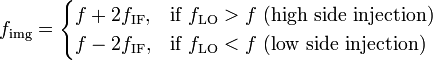
Image frequency (fimg)
One major disadvantage to the superheterodyne receiver is the problem of image frequency. In heterodyne receivers, an image frequency is an undesired input frequency equal to the station frequency plus twice the intermediate frequency. The image frequency results in two stations being received at the same time, thus producing interference. Image frequencies can be eliminated by sufficient attenuation on the incoming signal by the RF amplifier filter of the superheterodyne receiver.
 For example, an AM broadcast station at 580 kHz is tuned on a receiver with a 455 kHz IF. The local oscillator is tuned to 580 + 455 = 1035 kHz. But a signal at 580 + 455 + 455 = 1490 kHz is also 455 kHz away from the local oscillator; so both the desired signal and the image, when mixed with the local oscillator, will also appear at the intermediate frequency. This image frequency is within the AM broadcast band. Practical receivers have a tuning stage before the converter, to greatly reduce the amplitude of image frequency signals; additionally, broadcasting stations in the same area have their frequencies assigned to avoid such images.
The unwanted frequency is called the image of the wanted frequency, because it is the "mirror image" of the desired frequency reflected
 . A receiver with inadequate filtering at its input will pick up signals at two different frequencies simultaneously: the desired frequency and the image frequency. Any noise or random radio station at the image frequency can interfere with reception of the desired signal.
Early Autodyne receivers typically used IFs of only 150 kHz or so, as it was difficult to maintain reliable oscillation if higher frequencies were used. As a consequence, most Autodyne receivers needed quite elaborate antenna tuning networks, often involving double-tuned coils, to avoid image interference. Later superhets used tubes especially designed for oscillator/mixer use, which were able to work reliably with much higher IFs, reducing the problem of image interference and so allowing simpler and cheaper aerial tuning circuitry.
Sensitivity to the image frequency can be minimised only by (1) a filter that precedes the mixer or (2) a more complex mixer circuit [1] that suppresses the image. In most receivers this is accomplished by a bandpass filter in the RF front end. In many tunable receivers, the bandpass filter is tuned in tandem with the local oscillator.
Image rejection is an important factor in choosing the intermediate frequency of a receiver. The farther apart the bandpass frequency and the image frequency are, the more the bandpass filter will attenuate any interfering image signal. Since the frequency separation between the bandpass and the image frequency is
 , a higher intermediate frequency improves image rejection. It may be possible to use a high enough first IF that a fixed-tuned RF stage can reject any image signals.
The ability of a receiver to reject interfering signals at the image frequency is measured by the image rejection ratio. This is the ratio (in decibels) of the output of the receiver from a signal at the received frequency, to its output for an equal-strength signal at the image frequency.
1070 + (2x455KHz)= 1980KHz
1070 - (2x455KHz)= 160KHz
1980 and 150KHz are both image frequencies.
Interesting to note that we had many people call us to tell us that they were hearing aircraft comms interfering with out 97.7 MHz FM transmitter. The problem is that 119.1 MHz is Halifax approach. FM receivers have a 10.7 MHz IF.
97.7 + (2x10.7) = 119.1MHz
While tuning to 97.7 their radios would also pick up 119.1MHz and even tho it was AM the presence of the FM carrier on 97.7 allowed the audio to be decoded.
I got tired of having people tell that they did in fact NOT have a shitty receiver and that they wanted me to fix the issue at the transmitter site. :bdh: :headbang
From Wiki:
Image frequency (fimg)
One major disadvantage to the superheterodyne receiver is the problem of image frequency. In heterodyne receivers, an image frequency is an undesired input frequency equal to the station frequency plus twice the intermediate frequency. The image frequency results in two stations being received at the same time, thus producing interference. Image frequencies can be eliminated by sufficient attenuation on the incoming signal by the RF amplifier filter of the superheterodyne receiver.
The unwanted frequency is called the image of the wanted frequency, because it is the "mirror image" of the desired frequency reflected
Early Autodyne receivers typically used IFs of only 150 kHz or so, as it was difficult to maintain reliable oscillation if higher frequencies were used. As a consequence, most Autodyne receivers needed quite elaborate antenna tuning networks, often involving double-tuned coils, to avoid image interference. Later superhets used tubes especially designed for oscillator/mixer use, which were able to work reliably with much higher IFs, reducing the problem of image interference and so allowing simpler and cheaper aerial tuning circuitry.
Sensitivity to the image frequency can be minimised only by (1) a filter that precedes the mixer or (2) a more complex mixer circuit [1] that suppresses the image. In most receivers this is accomplished by a bandpass filter in the RF front end. In many tunable receivers, the bandpass filter is tuned in tandem with the local oscillator.
Image rejection is an important factor in choosing the intermediate frequency of a receiver. The farther apart the bandpass frequency and the image frequency are, the more the bandpass filter will attenuate any interfering image signal. Since the frequency separation between the bandpass and the image frequency is
The ability of a receiver to reject interfering signals at the image frequency is measured by the image rejection ratio. This is the ratio (in decibels) of the output of the receiver from a signal at the received frequency, to its output for an equal-strength signal at the image frequency.
Last edited:
Harmonics are exact MULTIPLES of the fundamental frequency therefore harmonics of 1070 KHz would fall on 2140, 3210, 4280 etc. What you heard was an image frequency. A receiver has an oscillator that tunes to a frequency offset from the actual received freq. by the difference in the IF freq. which is usually 455KHz. Sometimes a spur develops at twice that IF freq. and the receiver will pick up a station at two times the IF offset from where it should be. I suspect that you really heard it on 160KHz maybe? If it was 170KHz then your receiver must have a 450KHz IF.
1070 + (2x455KHz)= 1980KHz
1070 - (2x455KHz)= 160KHz
1980 and 150KHz are both image frequencies.
Interesting to note that we had many people call us to tell us that they were hearing aircraft comms interfering with out 97.7 MHz FM transmitter. The problem is that 119.1 MHz is Halifax approach. FM receivers have a 10.7 MHz IF.
97.7 + (2x10.7) = 119.1MHz
While tuning to 97.7 their radios would also pick up 119.1MHz and even tho it was AM the presence of the FM carrier on 97.7 allowed the audio to be decoded.
I got tired of having people tell that they did in fact NOT have a shitty receiver and that they wanted me to fix the issue at the transmitter site. :bdh: :headbang
From Wiki:
Image frequency (fimg)
One major disadvantage to the superheterodyne receiver is the problem of image frequency. In heterodyne receivers, an image frequency is an undesired input frequency equal to the station frequency plus twice the intermediate frequency. The image frequency results in two stations being received at the same time, thus producing interference. Image frequencies can be eliminated by sufficient attenuation on the incoming signal by the RF amplifier filter of the superheterodyne receiver.
For example, an AM broadcast station at 580 kHz is tuned on a receiver with a 455 kHz IF. The local oscillator is tuned to 580 + 455 = 1035 kHz. But a signal at 580 + 455 + 455 = 1490 kHz is also 455 kHz away from the local oscillator; so both the desired signal and the image, when mixed with the local oscillator, will also appear at the intermediate frequency. This image frequency is within the AM broadcast band. Practical receivers have a tuning stage before the converter, to greatly reduce the amplitude of image frequency signals; additionally, broadcasting stations in the same area have their frequencies assigned to avoid such images.
The unwanted frequency is called the image of the wanted frequency, because it is the "mirror image" of the desired frequency reflected. A receiver with inadequate filtering at its input will pick up signals at two different frequencies simultaneously: the desired frequency and the image frequency. Any noise or random radio station at the image frequency can interfere with reception of the desired signal.
Early Autodyne receivers typically used IFs of only 150 kHz or so, as it was difficult to maintain reliable oscillation if higher frequencies were used. As a consequence, most Autodyne receivers needed quite elaborate antenna tuning networks, often involving double-tuned coils, to avoid image interference. Later superhets used tubes especially designed for oscillator/mixer use, which were able to work reliably with much higher IFs, reducing the problem of image interference and so allowing simpler and cheaper aerial tuning circuitry.
Sensitivity to the image frequency can be minimised only by (1) a filter that precedes the mixer or (2) a more complex mixer circuit [1] that suppresses the image. In most receivers this is accomplished by a bandpass filter in the RF front end. In many tunable receivers, the bandpass filter is tuned in tandem with the local oscillator.
Image rejection is an important factor in choosing the intermediate frequency of a receiver. The farther apart the bandpass frequency and the image frequency are, the more the bandpass filter will attenuate any interfering image signal. Since the frequency separation between the bandpass and the image frequency is, a higher intermediate frequency improves image rejection. It may be possible to use a high enough first IF that a fixed-tuned RF stage can reject any image signals.
The ability of a receiver to reject interfering signals at the image frequency is measured by the image rejection ratio. This is the ratio (in decibels) of the output of the receiver from a signal at the received frequency, to its output for an equal-strength signal at the image frequency.
160-170khz it was strongest at 170.
So the handheld shortwave receiver is junk? Its far from perfect, it was just trippy to be up on a hillside on a jog and hear my fav AM station on 170khz when really they operate best on knx1.070Khz
That last bit is funny
160-170khz it was strongest at 170.
So the handheld shortwave receiver is junk? Its far from perfect, it was just trippy to be up on a hillside on a jog and hear my fav AM station on 170khz when really they operate best on knx1.070Khz
That last bit is funny
Not junk just not as good as it could be with about $0.99 in extra parts.
Not junk just not as good as it could be with about $0.99 in extra parts.
Grundig g5 brand new
Grundig g5 brand new
Completely irrelevant. Insufficient filtering before the first RF amp is the cause and VERY common especially in smaller portable radios.
Completely irrelevant. Insufficient filtering before the first RF amp is the cause and VERY common especially in smaller portable radios.
Unfortunately I just don't feel like lugging up a old helicrafters on my back to a hill top.
dxChat
- No one is chatting at the moment.
-
-
dxBot:boog351 has left the room.
-
@ BJ radionut:
June VHF
The American Radio Relay League (ARRL) is the national association for amateur radio, connecting hams around the U.S. with news, information and resources.www.arrl.org
-
-