• You can now help support WorldwideDX when you shop on Amazon at no additional cost to you! Simply follow this Shop on Amazon link first and a portion of any purchase is sent to WorldwideDX to help with site costs.

Using NPO/C0G caps for better SSB stability?

Robb

Honorary Member Silent Key
Dec 18, 2008
11,432
3,651
323
Silicon Valley CA, Storm Lake IA
Using NP0/C0G caps for better SSB stability?

Was researching the problem of warm-up and freq stability in the Ranger/Galaxy radios.

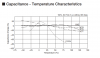
Came across a brochure from Murata that showed NPO monolythic cap stability compared to non-NPO caps.

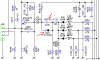
Since the Galaxy/Ranger radios use non-NPO caps in the oscillator circuits and the fact that the collective capacitance of that circuit determines freq and will shift wildly when cold or hot, thought I would bring it up as a topic.

I was wondering if replacing the cheap ceramic caps with the NPO monolythics would tighten up the freq instability problem. They are indicated as the proper part in UHF radios for freq stability and aren't that expensive to replace a dozen or more caps in the radio's oscillator circuits.
 

Attachments

  • C0G.PNG
    C0G.PNG
    41.8 KB · Views: 3
Last edited:

From Wikipedia:

Class 1 ceramic capacitors
Class 1 ceramic capacitors are accurate, temperature-compensating capacitors. They offer the most stable voltage, temperature, and to some extent, frequency. They have the lowest losses and therefore are especially suited for resonant circuit applications where stability is essential or where a precisely defined temperature coefficient is required, for example in compensating temperature effects for a circuit.


Ceramic capacitor - Wikipedia, the free encyclopedia

Point is, that you cannot find one C0G rated cap in the PLL, VCO, Loop Oscillator, or Carrier Oscillator in a Galaxy/Ranger radio.
Why is that; since they are so prone to drift?

These ('single layer disc') caps are the most commonly used for
general purpose circuits, but these non-NP0 types should be avoided in
frequency determining circuits
 

Attachments

  • Capacitor tutorial.pdf
    1.6 MB · Views: 5
Last edited:
From Wikipedia:

Class 1 ceramic capacitors
Class 1 ceramic capacitors are accurate, temperature-compensating capacitors. They offer the most stable voltage, temperature, and to some extent, frequency. They have the lowest losses and therefore are especially suited for resonant circuit applications where stability is essential or where a precisely defined temperature coefficient is required, for example in compensating temperature effects for a circuit.

Ceramic capacitor - Wikipedia, the free encyclopedia

Point is, that you cannot find one C0G rated cap in the PLL, VCO, Loop Oscillator, or Carrier Oscillator in a Galaxy/Ranger radio.
Why is that; since they are so prone to drift?

Price, maybe?
 
  • Like
Reactions: 1 person
Price, maybe?

Yeah, probably.

Just thinking that these Galaxy/Ranger radios can be fixed of this nagging drifting issue that they had for years if the capacitance in those circuits were more stable. Don't expect it to be w/o drift altogether; but a lot less of it sure would be welcome.

If one were to compare a Cobra 148GTL with a Galaxy DX 959 turning them both on one cold morning, the Cobra would be maybe 120hz off of center freq while the Galaxy might be off as much as 6 or 7 hundred hz. Why? Just thought the capacitance was off due to Galaxy using cheaper parts.

For example, this is the varactor diode (D49) in parallel with a disc cap (C130) that has the 'UJ' code in this diagram below. While C130 is a Class 1 cap and fairly stable, it is not nearly as stable as a "CG' (IOW, a C0G) would be in its place. Imagine that C133, 134, and 135 would also pull total circuit capacitance out and lend to drifting too if they are not stable at pre-warmup temperatures as a better cap would.

If I can find a supplier then I will get some C0G's of different values and see if it will make a difference.
Started this thread thinking that others have been here before and could offer up some insights - is all.
 

Attachments

  • varactor.PNG
    varactor.PNG
    61.2 KB · Views: 4
  • uj cg.PNG
    uj cg.PNG
    39.9 KB · Views: 4
Last edited:
Things like thermal drift in crystals and voltage regulators also shift frequency and is why capacitors with different temperature coefficients drift in different amounts and direction of drift to compensate. Notice C279 has a "CH" designation not listed on the chart. The slightest voltage change from the 8 volt regulator to the varactor diode or VCO can also cause this problem.

We need to identify the part of the circuit causing the most offending drift and either stabilize that or introduce an equal but opposite drift using a specific capacitor. Make sure the 8 volt rail is perfectly stable. Check the crystal for thermal drift. If it moves around a lot, consider replacing it or using the Motorola "crystal oven". Heat shrink wrap a 100 ohm 1/2 watt resistor to the side of the crystal and hit it with 12 volts to pre warm the crystal.
 
I agree. If all things were equal between the Cobra and the Galaxy there wouldn't be this drift problem. But if the crystals had better caps to ground that didn't vary much with temp, I tend to doubt that the crystal is to blame since they get them from the same vendors. But even the Cobra isn't using a special cap there.

Guess I can change out the zener on the voltage regulator to insure stable voltage; but voltage stability doesn't seem to be the problem.

The stability of the reference oscillator would be the first place to modify with monolithic C0G caps. Then the VCO, Loop Oscillator, and finally the Carrier Oscillator with the same treatment. But should all the disc caps be changed out; or just in selected locations? That is the real brain teaser here.

If this radio were to be built to gov't specs, I imagine they would all be changed out any part that kept the oscillator circuit as stable as possible. Which begs the next question: are these C0G parts unavailable and therefore why these radios are unstable? However, even the newer Cobra 148s don't seem to suffer drift/cold start as the Galaxy/Ranger does.

The next step is to identify all of the offending parts, locate a vendor, purchase parts, and then experiment . . .
 
Last edited:

dxChat
Help Users
  • No one is chatting at the moment.
  • dxBot:
    Tucker442 has left the room.
  • @ BJ radionut:
    LIVE 10:00 AM EST :cool:
  • @ Charles Edwards:
    I'm looking for factory settings 1 through 59 for a AT 5555 n2 or AT500 M2 I only wrote down half the values feel like a idiot I need help will be appreciated