• You can now help support WorldwideDX when you shop on Amazon at no additional cost to you! Simply follow this Shop on Amazon link first and a portion of any purchase is sent to WorldwideDX to help with site costs.

RF Sampler

The Unidapt RF Samplers are adjustable as well by loosening the lock ring on the BNC connector shaft then slide the BNC connector in or out for more or less sensitivity.

Good luck with your home brew unit (y)
Thanks I enjoy a challenge, plus if I buy all my equipment will I have a greater understanding (how it functions) as opposed to building parts of the system?
Amateur experimentation is why we have Ham Radio, without the pioneers or military no Citizens Band would exist, I see a growing shift towards SMT and the buy-it mentality instead of build-it, back before my day the manufacturers would supply schematics, now they want you to send it in or buy a new one...

Hams from the days gone would cry seeing this Science/Hobby turned into a dog & pony show for the larger corporations!
 
Old Crow Thank you, I will build the design published by K9EID.
That potentiometer to ground allows for adjustments to be made, what does the variable compensate for/ allow for over the fixed value. Different power levels? It basically forms a voltage divider I can see that, just curious why the added ability to change the resistance?
As I was going from SSB to Am the scope picture would change and to correct I had to use different resister values, so with the potentiometer its an easy fix. I built a few different ones using toroid's and this one was the best, similar to the Bird RF sampler I borrowed.
 
  • Like
Reactions: LeapFrog
As I was going from SSB to Am the scope picture would change and to correct I had to use different resister values, so with the potentiometer its an easy fix. I built a few different ones using toroid's and this one was the best, similar to the Bird RF sampler I borrowed.
Very Nice, I will throw one together & see if I have a 20k Pot or 10K Pot Laying around, are the resister values crucial or do you have some "lee-way"?
 
  • Like
Reactions: Steve_Buckeye
Very Nice, I will throw one together & see if I have a 20k Pot or 10K Pot Laying around, are the resister values crucial or do you have some "lee-way"?

Try different ones, the values are good starting points, that's what's this hobby is about. When you find a good combination share it with us. Try to use at least 1/4 watt components for a cb. For a hotter radio you might have avoid using direct circuits and go to coils and toroid's. I once tried an a/b switch, I tapped off the unused leg and it worked. Can be dangerous if you forget transmit to scope.
 
I use one that is a little different than most. It has a Demod port and sampler port. These connect to the X and Y input of your scope. The demod port will pick the audio off the carrier. This way you can look at both separately. w2aew has a video on it on YouTube.


index.php


Link to it on my site.
http://gokarters.com/smf/index.php?topic=2467.msg17740#msg17740
 
I use one that is a little different than most. It has a Demod port and sampler port. These connect to the X and Y input of your scope. The demod port will pick the audio off the carrier. This way you can look at both separately. w2aew has a video on it on YouTube.

Link to it on my site.
http://gokarters.com/smf/index.php?topic=2467.msg17740#msg17740
Great addition to the thread, thank you Radio Tech. Viewing the audio on the 'scope now that's going to be useful for experiments, and testing. I subscribed to w2aew's channel, he has many great videos.
 
Last edited:
"www.gokarters.com/smf
Visit my hobby forum"

Just got our old Manco "Dingo" Go Kart going again for my 13 year old son. He totally loves it!
Great, he will have fun. But please but safety first. I see too many kids hurt on these things. Back in the 90's that was my kart racing site. I raced the world karting association sanctioned tracks. Was also the local track tech man. I won 3 championships during my career. It was fun. Ran limited modified class at 106 mph 1 inch off the ground......
 
Old Crow Thank you, I will build the design published by K9EID.
That potentiometer to ground allows for adjustments to be made, what does the variable compensate for/ allow for over the fixed value. Different power levels? It basically forms a voltage divider I can see that, just curious why the added ability to change the resistance?

I added the pot for variable attenuation for a desired result through-out the bands
 
If some of you guys have 3 minutes to kill and wouldn't mind adding some comments... @ 0:58 the 1kHz tone is blaring so i'm putting a loud audio warning here..

Be very careful some of my green-ness may rub off (Haha Not!!)
I had the scope set to AC coupling and ch.1 set to "AC" while V/Div set to 1x & sec/Div set to .1 millisecond.
Does any of this sound about right?
Also sorry for the crappy video I need to work on my cinematography skills.


A Big Shout-out & A Thank You to everyone who posted/shared in this thread to allow the information to become more accessible for the masses.

-Sam aka Leap
 
Last edited:
  • Like
Reactions: 805 california
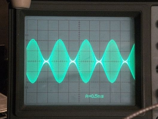
I don't like what I see but it is hard to tell. You need to adjust the scope's TRIGGER LEVEL so the display appears still instead of blurry and running back and forth the screen. Best to do this with a tone. You should be able to see a nice clean stable image. From what I can see it looks like you are way over 100% modulation. When the carrier pinches off in the middle and you see a bright flat spot in the middle that is when the carrier is pinched off due to overmodulation. If you set up the display to fill two large divisions on the screen with just unmodulated carrier then voice peaks will just fill four large divisions when you hit 100% modulation but regardless of what the peaks are you should never see the carrier pinch off in the middle.

100% modulation

AMenvelope.jpg


Overmodulation and carrier pinched off.

BC-1G-120%25-modulation-10-09-14.jpg
 
I don't like what I see but it is hard to tell. You need to adjust the scope's TRIGGER LEVEL so the display appears still instead of blurry and running back and forth the screen. Best to do this with a tone. You should be able to see a nice clean stable image. From what I can see it looks like you are way over 100% modulation. When the carrier pinches off in the middle and you see a bright flat spot in the middle that is when the carrier is pinched off due to overmodulation. If you set up the display to fill two large divisions on the screen with just unmodulated carrier then voice peaks will just fill four large divisions when you hit 100% modulation but regardless of what the peaks are you should never see the carrier pinch off in the middle.
Thank You Captain Kilowatt this is the answer I needed to hear.
EDIT: It the was trigger view settings, I just didn't know enough yesterday.


Thank You.
-Sam aka Leap
 
Last edited:

dxChat
Help Users
  • No one is chatting at the moment.
  • dxBot:
    Tucker442 has left the room.
  • @ BJ radionut:
    LIVE 10:00 AM EST :cool:
  • @ Charles Edwards:
    I'm looking for factory settings 1 through 59 for a AT 5555 n2 or AT500 M2 I only wrote down half the values feel like a idiot I need help will be appreciated