
You are using an out of date browser. It may not display this or other websites correctly.
You should upgrade or use an alternative browser.
You should upgrade or use an alternative browser.
-
You can now help support WorldwideDX when you shop on Amazon at no additional cost to you! Simply follow this Shop on Amazon link first and a portion of any purchase is sent to WorldwideDX to help with site costs.
-
The Father's Day Retevis RA89R Winner is Announced! Click Here for more info!
proper coax choke mobile..
- Thread starter Splash1
- Start date
First, there's no "one true way" of making a coaxial choke. There are several methods, the best one for you is the one that you can make easily, that works. After that, if you want to paint it purple, it's just fine.
The biggy is not to wind it too tightly. That produces something called 'migration', or the center conductor tends to migrate/move away from the center of the cable towards one side. I think you can see why that wouldn't be such a good idea, since carried to the extreme, it would mean a shorted cable.
There really isn't any firm/absolute way of telling you how many turns to make in that coil. That depends on too many variables. One ROT (rule of thumb) is more is better to some ridiculous degree. For 11 meters, something like 4 - 10 turns of coax ought'a work fine.
Another thing to remember is that the shape of the choke does make a little difference in how affective it is. If it's reasonably close to the 'typical' shape of a coil, that's good. Coiling the cable up like you would rope will work fine too.
Since you use a choke to keep 'stuff' off of the feed line (sort of), it should be placed as close to the antenna's feed point as is practical. If your antenna if roof mounted, squeezing a choke under the roof liner isn't the most practical thing to do, so don't. But if it will fit without really looking stupid, why not?
What's the best coax to use for a choke? Whatever you happen to have enough of, the same impedance as the rest of the feed line, of course. Or just coil up the 'extra' feed line you happen to have already running between antenna and radio.
Not all that complicated, huh?
- 'Doc

thanks for the reply Doc..i aready made one with about 6 turns without knowing the correct number just to see what would happen..befor i had common mode i figured becauce when i touched the meter or the cable while testing swr the needle would move..after the choke the needle doesnt move at all..i also noticed befor the choke when the roof was wet the swr went higher,after installing the choke and pouring water on the roof ,the swr stays the same..
B
BOOTY MONSTER
Guest
heres some good info on coils and center migration from The Ultimate Guide to 11 Meter CB Antennas
COIL INFO
Another reason SWR could vary is from the situation where the coax is acting as part of the antenna. Not a favorable or normal situation. The signal is traveling back down the outside of the of the coax braid (note power should only be traveling on the inside on the coax braid). Therefore, the coax is part of antenna system and changing the coax length will change the SWR. This situation is more likely to occur in mobile installations. You can try to eliminate this situation (called "Common mode currents") by winding an "RF Choke". Wind about 6ft of RG-213 or RG-8 into a coil (6 to 8 turns). For RG-58 use 4ft with 6 to 8 turns. Wind the coax up, placing each turn right next to one another. Use electrical tape to secure turns together. You should place these as close to the antenna as possible. Right at the antenna coax connection point being optimum. Most times, you can verify that you have common mode currents flowing back down the coax by grabbing hold of the coax while transmitting and moving the coax around. You can watch the SWR waver by moving the coax while transmitting (don't speak into mic!). You have to do this with all the doors closed from inside the vehicle. SWR should waver, if you notice that SWR jumps rapidily between two values, you might have a intermitant (bad) connection in the connectors (PL-259s) on the coax. In most cases of "common mode currents", just grabbing the coax will cause the SWR to change.
The "RF choke" described above stops the signal from traveling back down the outside of the coax. The signal inside the coax is * u n a f f e c t e d * by the choke (contrary to what you may have heard about coiling up excess coax). Common mode current kills antenna efficieny. You could have a decent SWR and not realize half your signal is being broadcast into you car (result very poor antenna performance). If your linear amplifier causes serious problems with your car's computer, lights, etc....you may have common mode currents. If moving the coax around the vehicle results in SWR change, this is a good indicator you have common mode currents flowing back down the coax line.
This doesn't happen often with base station antennas. Most base antennas have some type of device that will decouple the antenna from the feedline (gamma match, balun, etc.). Make sure you run your feedling (coax) straight down from the antenna, taking care not to run close to antenna to prevent "common mode" currents which could still occur if coax is oriented in a way to pick up strong antenna signal.
MIGRATION INFO
Coax Impedance
Again, the term impedance in "Coax Impedance" has different meaning...you can not measure it with your trusty Ohm meter. It is determined by the spacing (ratio) of the inner wire and outer braid. In CB service, the two impedance's mainly used are 50 Ohm and 75 Ohms.
lots of great info on that page !!!!
becauce i had common mode currents.
Is it unusual in a mobile with a large counter poise?
Not that it doesn't happen, but I haven't heard of it before in a mobile.
B
BOOTY MONSTER
Guest
" Another reason SWR could vary is from the situation where the coax is acting as part of the antenna. Not a favorable or normal situation. The signal is traveling back down the outside of the of the coax braid (note power should only be traveling on the inside on the coax braid). Therefore, the coax is part of antenna system and changing the coax length will change the SWR. This situation is more likely to occur in mobile installations. "
that line there gives me the impression that at least some of the folks that change coax length to change/lower their SWR actually have a common mode current problem .
since " The signal inside the coax is * u n a f f e c t e d * by the choke (contrary to what you may have heard about coiling up excess coax). " if the extra coax is available why not just do a choke to eliminate the possibility of CMC problems ?
on 11 meters whats the proper way to form a rf choke ? number of turns and diameter of coils.
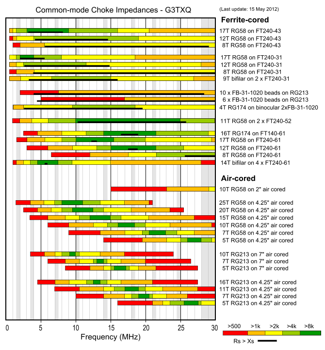
8 turns of RG58 on a FT240-61 ferrite ring. That will give you >4k Ohms of choking which will be resistive not reactive.
Problem with air wound ones is the choking is reactive and they're extremely narrow banded. Because it is reactive it has the possibility to increase common mode currents. Wrong diameter, two turns out and its as much use as a chocolate fireguard. For example 5 turns of RG213 on a 4.25" diameter core will give you 8k Ohms reactive choking on 11m but increase the number of turns on the same core to 7 turns and you've now only got 500 Ohms on 11m.
COURTESY OF G3TXQ - the ones with the black lines under the frequencies you are using indicate resistive choking where the black lines are and are the ones you want to be doing.
Well a choke balun is usually done on a form like PVC pipe say 4 inch diameter the actual diameter of the PVC is not as critical as making sure you use at 18 ft of coax and wind it snug on the form you can use tie wraps the ends to hold it simply by drilling 2 holes just far enough apart that the coax can be secured with ties that are fed through the holes. It works have used it many times and is referred to as a choke balun.Can you achieve the same effect (eg keeping RF off the coax) by installing a 1:1 Balun near the feed point of the mobile antenna?
dxChat
- No one is chatting at the moment.
-
-
-
dxBot:boog351 has left the room.
-
@ BJ radionut:
June VHF
The American Radio Relay League (ARRL) is the national association for amateur radio, connecting hams around the U.S. with news, information and resources.www.arrl.org
-