• You can now help support WorldwideDX when you shop on Amazon at no additional cost to you! Simply follow this Shop on Amazon link first and a portion of any purchase is sent to WorldwideDX to help with site costs.

Cobra 2000 GTL Smoking on SSB (literally)

LeapFrog

Wielding Hanlon's Razor
Feb 15, 2016
1,709
903
123
Anchorage, Alaska
OKay.. as the title says the radio wants to smoke (it won't blow a 4 amp fuse) itself when switched into SSB mode, I measured the voltage at the collectors of driver and final, and when I switch the radio to SSB the voltage shunts to ground and the current draw increase, a lot. This is in RX mode, it's enough to blow a 2 amp fuse but not a 4 amp fuse.


With VR10 adjusted for about 6 Volts the radio would only peak to 3 watts carrier and couldn't do 100% modulation, swinging backwards.
The best it'll perform is with 2 watts carrier going to 8 watts PEP, something is amiss!


I have a funny feeling that when I go to adjust the bias, I won't be able to.... lol
The radio will RX ssb, and TX a small amount on ssb.

Oh yeah, a little background on this particular 2000 GTL.

It was plugged in backwards with the fuse bypassed and the RPD fused itself, and a choke and a hand wound transformer, and several other parts fried before the owner unplugged it, eventually seeing the cloud of smoke.


So far I've rebuilt the power supply, recapped the entire radio, electrolytics & tantalums (phreak counter also, and diode update).
The audio IC was bad so it's been replaced, along with the PLL.


An awesome forum member helped me realize the poorly executed (major slide) clarifier mod was performed incorrectly and dragged the VCO preventing proper alignment "40CH. stretch", clarifier returned to factory and VCO + synthesizer aligned nearly perfectly.
It nows receives and transmits, but obviously with something seriously wrong.
I'm trying to save this radio & "get it out the mud", any (more) help from members is greatly appreciated!

The fine tune adjust on the clarifier operates in reverse?? I've switched the wires around to no avail!
Also the carrier was fluttering about an 1/8 of a Watt, strange..

I believe I should check the MB3756 for proper voltages on RX + TX.
And attempt the driver + final idle bias adjust.
I need to come up with an "at home solution" for some freeze spray, I don't have an I.R. camera to see exactly what is heating up when the radio is switched to SSB.
The current draw is over 2 amps as the collector voltage drops from "supply" to ground.

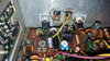
I've replaced two burned out chokes, and the bias transistor.
The final is a known good one, and the driver is operating.

Edit: it's been suggested to me that I should inspect the bias circuit closely.
 
Last edited:

Okay with the bias and RF PA circuits removed the
radio is consuming 220 mA through the fuse holder while off, and approx. 750 mA while in RX mode, this changes by about 20 mA between modes. (I'll have to look at the Sam's)

So if it was drawing over 2 amps in RX before, and only 750 mA now with the PA, Bias gutted, I'd say I removed the short, or the connection to the short... :sneaky:
I need to meter some components and find the failure.

I'm probably going to replace D76 and the potentiometer for ALC, because the wax migrated in this chassis, (it was stored in an attic on it's side I guess, or the PA section meltdown caused the PCB to heat so much the wax melted..) I don't trust an open potentiometer like that after seeing the wax had run down the main board, the wax may not respond to solvents, so cleaning could prove futile..


I should measure that MB3756 now..
Edit: 8 Volts okay
 
Last edited:
MV1Y and MV13YH? (they test ok)
Or D76?

Thanks guys!

The radio can now be operated in single sideband modes without any excessive current draw.

I am measuring 12.4 volts on the collectors of the driver and final at idle on A.M. which seems off if I recall correctly.

Just rebuilt the PA and Bias and attempted to set the driver bias...
It was going over 400 mA so something might be blown?
C151 and C152 replaced also :)
Playing with the potentiometer did show some adjustment.

I used the parts out of a newer 148 parts rig.
I measured the parts before I put them in and they were within tolerance, they just don't match the original schematic values..

But when I looked at the parts pile from what I pulled out of there, everything matched..

The manual may have some typos (like TP3 printed instead of TP8)

I didn't measure every part so I cannot say what exactly failed yet.
D76 was replaced with one from a parts radio.
 
Last edited:
You shouldn't be getting that much voltage on the collectors of the driver and final... I'd suspect a bad AM pass regulator. Replace the C1419 with a TIP41C or similar. Should be getting 2-7V depending on the state of VR10 on the collectors in AM mode.


~Cheers~
 
  • Like
Reactions: NZ8N and LeapFrog
You shouldn't be getting that much voltage on the collectors of the driver and final... I'd suspect a bad AM pass regulator. Replace the C1419 with a TIP41C or similar. Should be getting 2-7V depending on the state of VR10 on the collectors in AM mode.


~Cheers~
VR10 high leg 8.xx volts
wiper something like 6 volts.
It seems the buffer and the AM regulator have the correct voltages present.

C154 is not present, not sure if it should be. (don't see it silk screened on 148/Grant)
The 12 volts going to the collectors disappears when I pull TP7 & TP8.
Emitter of regulator has 5.7 Volts

Did a quick test for A.M. transmit, power was 3 Watts carrier to 12 P.E.P. with VR10 adjusted a little..
Tomorrow I'm going to 'scope out the driver and final and make sure they are both working.
Speaking of working I've got to hit the hay, so I'll mess with this some more later on in the week.

Edit: Cleaned up the thread.
Thanks Low_Boy, Exit13 & Kop, I appreciate the help guys. You are awesome.
Can't wait to look it over some more.

~All the Best!
 
Last edited:
  • Like
Reactions: NZ8N
Small update!
The orange wire feeding TP7, TP8 from the mode select switch provides 13.78 Volts regardless of mode selected, I believe I have a faulty mode switch, what do you say?
[I should review the schematic thoroughly before asking..]
 
Last edited:
The more-typical way for that switch to fail is as an open circuit, not a short.

Doesn't mean it can't.

A popular way to make the radio show the same peak power on AM as it does in SSB is to unhook the yellow wire feeding the final's collector circuit from the test point pin and solder it instead to the steady 13.8-Volt supply. Makes the final into a linear stage in AM mode, with only the driver transistor being modulated.

Just a thought.

73
 
  • Like
Reactions: LeapFrog
The more-typical way for that switch to fail is as an open circuit, not a short.

Doesn't mean it can't.

A popular way to make the radio show the same peak power on AM as it does in SSB is to unhook the yellow wire feeding the final's collector circuit from the test point pin and solder it instead to the steady 13.8-Volt supply. Makes the final into a linear stage in AM mode, with only the driver transistor being modulated.

Just a thought.

73
I understand your run down, the final is not "volted".

This radio has seen a tortured past, many things have been found failed/misadjusted.
I'm doing my best to repair it and return it close to "stock", I've been removing mods as I find them.

My issue is a steady 13.7 volts on the collectors of both driver and final while in AM mode with proper carrier voltage from VR10 circuit, good TR41 and buffer TR.
Narrowed problem to TP7/TP8, should I have 6 volts here on AM?
Thank You Nomad..

..Back to the schematic I go.
 
Last edited:
Update:

Got the radio nearly sorted, AM voltage correct and driver/final bias adjusted to service manual specifications. (y)

I just needed to do the final alignment and then the damn channel display decided to take a dive (two segments aren't lighting); this happened while I was testing radio over the course of a day or two.

So now I've got to see if the nearly 40 year old channel LED is at fault or channel switch itself! :mad:

The radio is fully operational and is no longer a "fire hazard" while in SSB mode! :D
Oh the joys of working on older solid state gear, lol. :)

One odd thing I noticed, the radio works with an external DC power supply connected, even if the main power switch isn't turned on, I'll have to consult the schematic to see if this behavior is normal.
 

dxChat
Help Users
  • No one is chatting at the moment.
  • dxBot:
    Tucker442 has left the room.
  • @ BJ radionut:
    LIVE 10:00 AM EST :cool:
  • @ Charles Edwards:
    I'm looking for factory settings 1 through 59 for a AT 5555 n2 or AT500 M2 I only wrote down half the values feel like a idiot I need help will be appreciated