• You can now help support WorldwideDX when you shop on Amazon at no additional cost to you! Simply follow this Shop on Amazon link first and a portion of any purchase is sent to WorldwideDX to help with site costs.

Cobra 148 GTL 7.8000 MHz issue

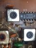
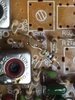
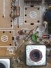
The R212...lol. To tell you the truth...my head is swimming but I'm going to beat this thing. Ok...first we had the frequency reversal on the schematics going into the mixer IC5. Now. looking at the silk screening on the board. I have diodes where resistors were, capacitors where diodes were and we have this R212 thing. All three pics are of made in Malaysia boards. The top pic is of the radio I am working on. The two below are from the parts bin but have a clearer view of the components. Take a look in the area between the 7.8000MHz filter output to the mixer. looks like they had to jumper the 2 frequencies to the other inputs of IC5.
Anyways, I replaced the 7.8000Mhz crystal filter. I had nothing coming out it in the test radio. I have installed a used crystal filter in this 148 GTL and I now have 7.8000MHz coming out of the filter. Tracing back from IC3 Pin7 to the output of the crystal filter I have the 7.8000MHz. But now it takes a different route than what is in the schematic so I am making my own by tracing the signal from the crystal filter down to the mixer input.
The +8V TX is coming off R212 before it even hits R191.
 

Attachments

  • IMG_4780.JPG
    IMG_4780.JPG
    188.8 KB · Views: 8
  • IMG_4778.JPG
    IMG_4778.JPG
    266.7 KB · Views: 7
  • IMG_4779.JPG
    IMG_4779.JPG
    255.9 KB · Views: 6
I did some testing on the filter while it was removed because I was wondering the same thing...if the frequency was too far off that it probably wouldn't pass the signal. This crystal filter passes 7.798500 to 7.801500 MHz
 
Of course they are different chips with different specs.

... [ ... ] ...

(these emitters aren't connected internally). Some radios tie them directly without a 100 ohm resistor (Galaxy 88 for instance then a 1k to ground to increase gain). Still, a resistor from either pin 10 or 12, to ground, increases current through the LTP and increases conversion gain. It's right in the datasheets of both components how that works. Those images of the IC internals you posted are not accurate.

You catching this @Unit 75???

@blasphemy000 - the diagrams where not designed to be functional - the "coloring" portion of the graphic was to show the orientation of those two resistors used to connect the cells to the other for combiner operation...

Now as techs', we are not interested in the internal package its not what I was after, the externals was the point of the posts. The two resistors. If one opens - they generate a separate issue and can throw people for a loop - they are only 1/6th if not 1/8th watt rated. So if you have an open coil, then the current draw in this portion can pop the winds of that wind like a fuse and the only tell-tale you've got is the open coil - well are the resistors ok?

Now thank you for catching the "Mirroing" because as I've found others trying to "visualize" the very points I can easily see in the differences between schematics and the actual boards - raise questions that I think are addressed othwerwise by how the graphic presents the part. Functionality aside... see the amber line is not green for typical ground - it's part of the mixer input to "gate" against...for the subtraction...

Now, since I don't physically have a 148 here to look at myself, the only thing that I have is the schematics. So any assumptions made could be wrong if there are errors or omissions in the diagrams, such as the one we found at the start with the pin numbers flip-flopped.
I'm not trying to be ignorant here, and I'm far from knowing everything, but I'm pretty good with different varieties of Gilbert cells.

73s

I'm cool with this, just remember I may not say it (the repair or functionality) the way others might want to hear - I learned what I know from the ground up...reverse engineering the parts in my own way of understanding - not a lot of people understand this approach. Too many people get left behind when technology starts to "fix itself" thru automation and refining being left to the machines themselves - they are only as good as the programming put into them to do this.

So welcome to the "Human factor" of explanation - I'll stay out of your way...
 
...made in Malaysia boards...

I think we found the disconnect between what you have on your bench and the papers I'm looking at here. That board is a Ranger/RCI board, and from what I'm told, this is the correct schematic here.

http://www.cbtricks.com/radios/rci/tr_296gk_dx/graphics/tr_296gk_dx_sm_sch.pdf

On this board R212 is the 1.5k current limiting resistor that feeds the TX8V into D53 to turn it on. While the signal from the filter actually passes through the 330 ohm R191 reducing it into the can. I think we're looking at the same radio now, hopefully that will help things along.

Andy: I'm 100% self taught also. What I know has been learned from reading books, online resources, reverse engineering the radios that I own, and building my own homebrew rigs. Everybody describes things differently, that's for sure, and no worries there. In my journeys though, I've found it much easier to understand the circuitry surrounding an IC once I understood the basic blocks inside the IC. Sometimes understanding beyond the block level is required, and is the case for these mixers. For visual representations to be understood, they need to be accurate. Since we discovered that Unit 75 has a Malaysian board, it looks like R190 is the 100 ohm that connects pins 10 & 12, and R211 is a 1k ohm from pin 10 to ground that is increasing the conversion gain.

73s
 
  • Like
Reactions: Unit 75
Ok. Found a cold solder joint at a junction. I now have 7.8000MHz out of the crystal filter all the way down to R191 (330ohm) on the top side then it disappears. That is as far as it goes. I have my +8V TX AM at one side of R212 and my .680V TX AM on the diode side of R212.
 
Remember that D53 is an RF switch. Kinda like a PIN diode - the line that uses the 330 ohm resistor also uses a 0.022uF (223) Disc cap C54 - to block it's DC so it doesn't turn on the RX side that uses D20

If it gets goofy, is can block the RF because it's junction is toast...
 
Yes. I remember about D53. D53 becomes forward biased as long as you have the +8V TX present to pass the 7.8000MHz signal thru it into the mixer. Interesting about those 223 caps. I see how that works now. Thanks. Why is the 7.8000MHz signal not passing thru R191 even though D53 has been forward biased? Does it have to do with the peaking coil? If the peaking coil was defective, would I still have the 7.8000MHz signal on the D53/R191 junction? I'm not sure if the coil had been functional and tuned to resonance if that might not help pull the signal thru. Or is the 7.8000Mhz signal too weak in amplitude to pass through the component.
 
Last edited:
There are several forks in the post you just made...

The D53 will pass RF as long as it drains off at a given rate faster than the 1.5K and 330 ohm resistor act upon it. So the coil then will sink this current - very small but enough of one to allow the 7.8MHz to pass relatively unhindered thru into the coil - which then couples to the tank side of the S042P or (insert favorite mixer chip here).

So if D53's junction is ok, then it's ability to RECTIFY is also present.

Just the D53 Rectification THRESHOLD (where the diodes PN junction acts like a valve - conducting only one way) has to be overcome by the DC current R191 is providing (lifting the bias) - yet not as strong as if the DC current - or power flow - is greater than the RF signal D53 is supposed to pass.

  • This is what I meant by the "washing" - it's an effect where the RF signal is too weak to pass along the line so the DC current and power simply remove, or wash off the signal from the line.

You don't need a lot of voltage - just enough to allow Peak 2 Peak and Trough 2 Trough levels of your SELECTED RF signal to pass thru.

The Rectification of the 7.8MHz signal will simply turn it back into a DC value and skew any efforts to couple the signal riding along on the DC trickle charge present.

If the bias voltage is greater than the RECIFICATION threshold, the diode will simply act as a pass thru - just like a switch. Because the Barrier that D53 has, is not interfering with the passage of DC and RF at the same time...

If D53 is bad, both conditions above can show up if the DIODE is SHORTED, if it's open then the Diode simply will not pass any current nor RF - it's like an open fuse.

If the power of the DC presence is too high, the coil cannot get enough RF signal to couple to the tank circuit for the Mixer chip to work with.

It can mean the coil is OPEN - blown open...
Coil shorted to a separate wind - excessive current...
Coil wind on Mixer side can also show the above traits.

So you may need to pull the can and it's shield and look into this.

You mentioned the internal cap - in my experiences, when a radio key up and stays keyed while you're tuning it - it means the coil may need to be replaced. This section can cause a local oscillation because it resonates on itself, the mixer tends to "loop" or oscillate on itself if the peaking was not done right. This can generate a lot of heat and not just blow the cap but literally DEFORM the coil winds from the excessive RF heating .

If you look back on all the post I've done in this thread, I've left you several trails of bread crumbs to help you determine the fault. I hope this doesn't go into a while goose chase but as I re-read, you seem to get a signal - just not the one you want which leaves me to wonder if your first premise of a bad coil was just the beginning of a much bigger tip of an iceberg that sinks the Titanic...(your radio)

Review the "Grant XL" post of where I say the Grant has this too - note the use of a Diode on one of the input lines - Anode to the power feed, to help quench RF loop problems of oscillations as well as prevent power reversal issues.
 
  • Like
Reactions: Unit 75
Ok. It looks good. I replaced the can (again) going into the SO24P pins 7 and 8. I can now read the correct 27.xxxMHz signals from ch1 to ch40 at the antenna jack. I have other issues, as you might have expected...but I will track them down. Hey, I cannot thank you enough for your input, guys. Not only did it fix the 7.8MHz input to the mixer issue.... but gave me a better understanding of "how and why" that part of the circuit functions which will make things much easier for me when I come across a similar 7.8MHz problem in one of these radios!! CHEERS! and thanks again :)
-75
 

dxChat
Help Users
  • No one is chatting at the moment.
  • @ Wildcat27:
    Hello I have a old school 2950 receives great on all modes and transmits great on AM but no transmit on SSB. Does anyone have any idea?
  • @ ButtFuzz:
    Good evening from Sunny Salem! What’s shaking?