• You can now help support WorldwideDX when you shop on Amazon at no additional cost to you! Simply follow this Shop on Amazon link first and a portion of any purchase is sent to WorldwideDX to help with site costs.

COBRA 2000 GTL channel mod wire off?

Crambone

Well-Known Member
Jan 22, 2019
486
155
53
55
My COBRA has the upper and lower channels added via the NB and CB switches. One of the wires became unattached on the underside and Im not sure were it goes?
 

Attachments

  • IMG_2141.png
    IMG_2141.png
    5.7 MB · Views: 31
  • IMG_2142.png
    IMG_2142.png
    7.6 MB · Views: 31
  • IMG_2143.png
    IMG_2143.png
    6.1 MB · Views: 30
  • IMG_2144.png
    IMG_2144.png
    5.8 MB · Views: 29

if its the wire that became disconnected from the solder side of the PC board, it goes to pin 10 of the PLL chip.
its that pin right next to the one with the yellow wire on it. it's the first pin on that side of the PLL chip.
LC
 
Pretty sure LC is right about pin 10. It was not connected in the factory setup, and does not have a foil pad around the chip pin. Makes it tricky to attach the wire, since you can solder only to the tiny pin, and not to the full surface of a foil pad.

This pin moves the radio up 64 channels when it is grounded in this radio.

73
 
  • Like
Reactions: 357magnum
So now Im experiencing a a power issue!!!!!!! This started before even touching the wire for the channel mod thats still hanging. UHHHHHH
The clock lights up with the time with power switch off but when I turn the radio on its popping the fuse 3A 250V.

Im showing 13.6 VDc on orange and white wire and ground on black. if I put the meter on Continuity I"m showing continuity across the orange and black and the white and black. Im very new to this but I dont believe i should see that? Im guessing when I close the power button its a dead short?
 

Attachments

  • COBRA NO POWER.JPG
    COBRA NO POWER.JPG
    1.1 MB · Views: 13
yes you definitely have a problem.
the power switch in the 2000GTL switches ground and should not have any voltage present on the switch terminals.
either something is connected wrong or you have a shorted component.

if you want to fix radios, you can't get away from learning how to read schematic diagrams.
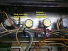
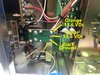
here is a shot of the section of the 2000 that you are dealing with:
Capture.PNG

notice S401 and that it is connecting a ground on the power supply board to the main PC board when it is turned on.

If C302 on the power supply board was shorted, then you would get the problem you have now, but that doesn't necessarily mean that's what you have going on.
could be other things.

start your search for bad components on that little power supply board, which includes that big transistor underneath the radio.
do a google search for how to test transistors with a multimeter.

you will have to unsolder the parts from the board before you test them.
testing capacitors and resistors can also be done on a multimeter, again google is your friend here.
LC
 
Something on the radio's main circuit board is shorted.

Not an easy troubleshooting job. Like LC says, you unsolder points in the power circuit, one by one in the "downstream" direction from where the power feeds into the main circuit board. Being able to follow the schematic diagram is a big help for that.

One quick thing to try first is the calibrated eyeball. Look for an electrolytic capacitor that has a bulge, or a layer of tan-colored powder on the surfaces below where it's mounted. If the part leaks the liquid inside, the dissolved solids in the liquid will appear as a brown to tan layer of dusty powder when it dries out, surrounding the part. The factory used a brown contact cement to reinforce larger parts by gluing them down to the pc board. Not the same thing.

Any time I hear this description I think LIGHTNING.....

Any visible scorch marks around the parts around where the AC line cord comes into the cabinet suggests a lightning surge that came down the power cord into the radio.

Have a very close look at the solder side of the circuit board. Around the edge you'll see screws holding the board to the metal chassis. On the top side of the board are ceramic disc capacitors that have one lead connected to those ground screws. Small scorch marks, or 'chinks' missing from the rim of the part indicate surge damage.

My favorite tool for this task is a regulated power supply that has a current limit of 1 Amp and a voltmeter on the front. It hooks to the external DC power-cord socket, and the switch moved from "AC" to "DC".

Saves time to watch the meter on the front of the power supply as you unhook points in the radio's power supply path. The limiter in the power supply will drop the output voltage, to hold the current down to the limit. If the voltage jumps up on the external supply, you cleared the short. Next, you put back that connection and take loose the next one "downstream" from it. Eventually this will lead you to the fault.

Assuming, of course that there is only one shorted component in the radio.

Lightning can hammer multiple parts in the radio.

Let's hope that's not what happened to this one.

73
 
  • Like
Reactions: Woody-202

dxChat
Help Users
  • No one is chatting at the moment.
  • dxBot:
    Tucker442 has left the room.
  • @ BJ radionut:
    LIVE 10:00 AM EST :cool:
  • @ Charles Edwards:
    I'm looking for factory settings 1 through 59 for a AT 5555 n2 or AT500 M2 I only wrote down half the values feel like a idiot I need help will be appreciated