• You can now help support WorldwideDX when you shop on Amazon at no additional cost to you! Simply follow this Shop on Amazon link first and a portion of any purchase is sent to WorldwideDX to help with site costs.

Francis 8' Wheeler Dealer Antenna

On my calipers the wire Dia is 1/64 of a inch.

I never tried to measure the wire diameter for my FWD, but I do remember back then the wire was very thin. I've suggested it might be 1/32" inch but never imagined it to be closer to 1/2 the diameter I used in my earlier posted model. Again, the wire was also very hard, like stainless steel wire. Your picture shows the wire looks like copper, so I think maybe the Francis antenna uses copper plated stainless steel wires...or else they used a very strong fiberglass back then. :rolleyes:

I did break apart the top broken off piece of the antenna and from that it "looks" like the three wires are offset to one side of the FG.

That is very good news Jeff.

Next I have to fix my model. With this new wire diameter, I will tweak the spacing so the three wires and spaces will fit within a half of the Fiberglass diameter you gave me a while back. I just hope the model does not crash on me.

Thanks for your help Jeff.
 
Last edited:
  • Like
Reactions: 2NC995
Thanks again Jeff for the dimensions.

I finally got the model to show the 3 wires #2,#3,#4 and 3 spaces to all fit within 1/2 of the FG diameter at the base which = 0.375" inches. I was a little surprised to see this ratio worked out to make the space to wire ratio = 3:1 on the money.

Spaces = 0.046875" / Wires = 0.015625" = 3:1

The dimensions, that I don't know for sure, are for the differences in wire lengths. I think I have the wire lengths very close to correct however, but I can't prove it.
 

Attachments

  • Latest Francis Fix model vs. my Marconi 4x with 4 x 10²'' whips.pdf
    1.9 MB · Views: 13
I am going to start by saying that my good Kodak camera I went and retrieved from storage has died.
That is a bummer.
Now I am stuck with the one on my phone, and has no macro mode for close up pictures.
And I can not get it to focus UGH!
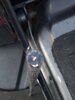
Picture 1
Shows the wire placement right above the 3/8-24 connector.
The 3 wires are centered in the FG blank.
The second picture is 48" above the top of the same connector.

Note there is no separation in between the 3 wires.
Another picture shows the cross section at 76 inches.
In this photo you can now see that the 3 wires are now offset too one side of the FG blank.
They still do not show 3 separate wires, they are side by side each other.
Right above this is where the FG shattered.
There is about a 7 inch section that is splintered and destroyed and it is not possible to tell were in the blank the wires were positioned.
The rest of the top of the whip ( from this point to the 96 inch top) was wedged in the carport structure and I ripped the bottom part out and left the rest stuck there.
I have the other good antenna on my truck now.
As I said before I have looked very carefully at the out side of the blank and can find no place were the wires are exposed in the taper as described in the Francis patent.
This afternoon I removed the antenna and took off the small red cap covering the tip.
I took a file and removed approx 1/16 of a inch of the blank.
I found the wires.
Yes.
I said wires.
The last picture is the antenna at the 96 inch termation and looking at it with a magnifying glass you can see all 3 wires at the top of the antenna.
This does not match the drawing that Eddie posted from the patent info earlier in this thread.
Now.
There is advertising from the past that says there were models made that were double quarter waves and triple quarter waves.
There is also ads that said the triple quarter waves were grey or red/orange.
I had been told by a old retailer that at some point Francis started making them all triple quarter waves to simplify production.
We know that Richard Francis said when the antenna company was up for sale that it would be hard for the new company that purchased the rights to the antenna to build if they did not buy the manufacturing equipment at the same time.
I can not date the manufacturer of these two antennas.
I bought them both from a shop in NC sometime in between 2004 /2005.
It was the last two he had and I have no way of knowing how long they had been in his stock.
So even after all of this we have more questions than answers.
Did the new owners by the equipment?
When did Francis alter the antennas to make them all triple quarter waves?
As Eddie said before, was this taper that made the 3 wires different lengths described in the patent info just placed there as part of the design, but not actually used?
At what time did the new owners of Francis antennas sell out old inventory and start selling antennas made on different equipment?
Did they stick with the original design?


73
Jeff
IMG952019121595124558.jpg

This picture above is right above the 3/8-24 connector.
The one below shows the wires at the 4 foot cut.
The one with the magnifying glass, if you zoom in shows the 3 wires at the top of the good 96 inch whip.
 

Attachments

  • IMG952019121595124848.jpg
    IMG952019121595124848.jpg
    85 KB · Views: 11
  • image000000.jpg
    image000000.jpg
    114.1 KB · Views: 12
  • Like
Reactions: 2NC995
This picture is on the broken antenna that shows were the wires are offset at the 76 inch cut.
Look at the 3 copper wires of to one side.
Disregard the two bright spots on the photo.
Again sorry for poor picture quality.

73
Jeff
 

Attachments

  • IMG952019121595132132.jpg
    IMG952019121595132132.jpg
    95.4 KB · Views: 18
Jeff, I bought my Francis whips back when I was only working mobiles, and that was back before the 80's. You got your antennas in 2004/2005. What if the black antennas you have were produced by the outfit that bought the Francis brand? I think we have heard, at least two stories and maybe more, about the history for this antenna over time.

I have not tried an idea like your images suggest, but I would guess the 3 wires could be touching, with no spacing, and responding similar to a thicker single element, and who would really know?

Surprisingly, my models with the 3 very small wires and 3 very small spaces shows very little difference other than a bandwidth increase. Now with the Patent, we now know that Francis was pushing for an increased bandwidth with very little loss in gain.

In the real world we've also heard many reports that the Francis WD/Amazer works very well, even compared to a full 1/4 wave radiator.

Thanks for the new information Jeff. Having 3 wires without spacing may be very possible and still preform great. With that said...I wonder what the real story behind the stopping of production was. I might have been a sign-of-the-times event that happened with shipping cost...just like we have also heard.
 
  • Like
Reactions: 2NC995
Disregard the two bright spots on the photo.
Again sorry for poor picture quality.

I mentioned this earlier about taking pictures. Several years ago I tried to take some close up pictures of my WD showing the wire in the side of the radiator and the tip, but the flash rendered the images useless.
 
  • Like
Reactions: 2NC995
Dan. my idea for wire position was taken form one of the 3 wire ideas noted in the Patent. Can you describe what you imagined?

Absolutely, I was just making a screen capture of the patent.

This is the arrangement I expected to see...and is this what you were working with??

3FC172E0-281E-434C-8CD2-1BA342D101E3.png
 
My thoughts were based on the after-the-fact grinding that was done to create the different length elements. That would be quite easy to do with the three parallel and off-center wires.

A different illustration from the patent is much closer, now that I see Jeff’s photos:


0EC262BA-F7E4-48D3-9777-A157224EF9CE.jpeg
 
My thoughts were based on the after-the-fact grinding that was done to create the different length elements. That would be quite easy to do with the three parallel and off-center wires.

A different illustration from the patent is much closer, now that I see Jeff’s photos:


View attachment 32584

That is certainly possible.

However in your 2nd image you will see wires that appear to be different in diameters with two wires having some insulation, like varnish, to keep the wires from physically touching.

I took your example of construction having 3 wires of equal length creating a similar response to the 3 wires of equal diameters and cut at different overall lengths that I've modeled.
 
  • Like
Reactions: 2NC995
I’d guess your speculation that they may have modified the design at some point is likely.

Somewhere in this thread I seem to remember you or someone else posting about the ground tip and observing a wire out the side. While I don’t remember the exact details, it was another tidbit that led to my expectation of seeing the first image.

I can’t help but wonder how much of the patent is just fluff, and how much actually makes a difference. It’s hard for me to see the tiny changes in wire diameter amounting to much. Of course, having two insulated and one not insulated also changes the relative spacing between the three..enough to change the results, or just a way to save a couple bucks on one of three spools of wire? We’ll probably never know.
 
Eddie
I don't know when or who with these 2 antennas.
I have no solid info on when the new company started production, or if they did or did not buy the equipment that Francis used.
It is stamped Francis on the connector, but that really means nothing.
And no positive info if the new company kept making them the way the originals were built, or just built them as cheap as possible.
All 3 wires are the same diameters measured with a digital caliper.
All 3 wires are coated with varnish.
I have scraped the wires with a knife and they look to be copper, not copper coated steel.
I wish there was some one alive that was associated with, or worked for Francis back in the day.
I can only report what I have in the 2 samples that I have in my hands now.
In the past I had other Francis antennas but never looked at them this way.
It would be interesting to see the construction of a pre 80's antenna.
It still stands that many have used this type of antenna and reported good results.
I have used them and still do and find them just as good as a 1/4 wave steel whip.
Thank you Eddie for the time you have invested in this project.
I will continue to look for more info in the future and report back here if anything new comes to light.
If anyone else has a old Francis antenna they could take detailed pictures of or info to add, please reply here.


73
Jeff
 

dxChat
Help Users
  • No one is chatting at the moment.
  • @ Wildcat27:
    Hello I have a old school 2950 receives great on all modes and transmits great on AM but no transmit on SSB. Does anyone have any idea?
  • @ ButtFuzz:
    Good evening from Sunny Salem! What’s shaking?
  • dxBot:
    63Sprint has left the room.
  • dxBot:
    kennyjames 0151 has left the room.