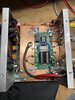
I just wanted to share my recent build using a cheap $35 kit off of eBay.
I also bought a 100W BPF to go with it for an additional $50 or so, and a 2-pill case from ICA manufacturing and I now have what seems to be a decent little amp. I'm getting 100W+ on all bands using my FT-817 to drive it.
I don't have a spectrum analyzer yet to see how clean it is, but on air reports have been great. My fist contact was a guy in Brazil and he gave me a 5/9 from North Idaho. Input SWR seems perfect, I've read other saying they've had high input swr, but that isn't the case for me.
What's really interesting is the device, it uses a MRF9120. Looking at the data sheet it appears this device was meant for 880MHz @26v 120W. I'm easily getting 100W @14v on HF.
Anyone else played around with these kits?