
You are using an out of date browser. It may not display this or other websites correctly.
You should upgrade or use an alternative browser.
You should upgrade or use an alternative browser.
-
You can now help support WorldwideDX when you shop on Amazon at no additional cost to you! Simply follow this Shop on Amazon link first and a portion of any purchase is sent to WorldwideDX to help with site costs.
-
Retevis is giving away a new RA89R for Father's Day! Click Here for more info!
Palomar 300a transformer
- Thread starter Staybolt
- Start date
Nope.
About 280 Volts AC on the HV winding is more or less your upper limit for that 300A.
The math works this way: Your two filter caps add up to a 900-Volt DC rating. In practice you never want to run the filter capacitors above 90 percent of the marked voltage rating. This rounds off more or less to 810 Volts DC.
The AC voltage feeding into the full-wave doubler circuit produces a DC voltage equal to 2.828 times the AC input from the HV winding. This factor times 280 Volts AC is 790 Volts. Gives you some safety margin if the line voltage on your wall outlet is a little higher than the typical voltage in 1975.
A 350-Volt winding feeding into this circuit gets you 990 Volts. Using the 90 percent rule, your filter capacitors' voltage ratings must now be at least 1100 Volts. And that means two caps rated for 550 Volts each. Good luck finding those.
You can't just stack three caps in series to get the rating, since the full-wave voltage doubler circuit is really two half-wave rectifier circuits in series. Gotta have a separate capacitor for each half of the circuit.
I suppose you could stack two 300-Volt caps in place of each single 450-Volt cap in the original circuit. Not sure where you'll put four of those in the space provided.
A 280-Volt transformer rating is pretty much the upper limit to use the original HV circuit and parts.
And if you choose to redesign the HV rectifier and filter circuits completely, this widens your range of possible substitutes.
Never say never. Just a matter of how much redesign you're willing to undertake.
73

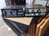
Sweet, thank you. I swapped face plates last night since I like the black better and the newer white face unit was very clean inside so I did the swap.Tokin,
You are correct.
73
David
Attachments
Tokin,
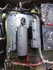
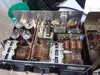
That is one of the cleanest 300A’s I’ve ever seen. Looks great!
I’m partial to the black face Palomar myself.

73
David
That is one of the cleanest 300A’s I’ve ever seen. Looks great!
I’m partial to the black face Palomar myself.
73
David
Thats what I said when I saw it on ebay. Its not perfect but its obviously never been ran hard or been in a smokers house. Its definitely one worth restoring. New tubes are next.Tokin,
That is one of the cleanest 300A’s I’ve ever seen. Looks great!
I’m partial to the black face Palomar myself.
View attachment 32690
73
David
Great info here I have transformer with 440 VAC out the HV secondary output and of course that too much Jolts of Volts for the voltage doubler.
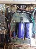
So this things uses a relay R4 to switch the primary voltage to the diodes and filter caps, as a PTT function. I would think this is to allow the tubes to load down the HV B+ as not to over voltage the two 450 VDC Power Supply Caps, while idling.
No wonder it was cheap on E-Pay, Yeah the caps were toast when I got and the 30 amp fuse was blown, oh good! Probably need to wire the diodes for a full wave bridge. Somebodies golden screw driver was way out of calibration. More to follow, oh charming! Thanks for the great info on the power transformer.
Jay in the Great Mojave Desert
you know where to get the 2-peice transmitters? i got the amp but no powersupplyGreat info here I have transformer with 440 VAC out the HV secondary output and of course that too much Jolts of Volts for the voltage doubler.
So this things uses a relay R4 to switch the primary voltage to the diodes and filter caps, as a PTT function. I would think this is to allow the tubes to load down the HV B+ as not to over voltage the two 450 VDC Power Supply Caps, while idling.
No wonder it was cheap on E-Pay, Yeah the caps were toast when I got and the 30 amp fuse was blown, oh good! Probably need to wire the diodes for a full wave bridge. Somebodies golden screw driver was way out of calibration. More to follow, oh charming! Thanks for the great info on the power transformer.
Jay in the Great Mojave Desert

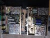
The power supply is a Transformer, not a complete power supply. As NoMadradio said the output of the Transformer High Voltage should be no more than 280 Volts.
How ever my Transformer has a output of 440 volts allowing a Power Supply output voltage of 1200 volts which will burn up the power supply filter capacitors Big Time. This Transformer is the wrong transformer to be used with a full wave voltage doubler circuit. It would work with a full wave bridge rectifier circuit making the 440 volts x 1.41 = 620 Volts DC. The point here is this may indicate my transformer is the wrong one, or there is a different configuration of the Palomar 300A Linear Amplifier. Who knows what the production configurations are. I own two Palomar 300A Amps, there big time different from each other. They use 3 or 4 relays that go bad and this amp can be a nightmere to fix with all the switching that goes on inside them.
A new transformer could be ordered and used, but again with these older amps you end up with more money that what they are worth.
So before you run down a Palomar 300A Transformer it needs to be checked with a tech before its plugged in and you smoke of two 40 dollar capacitors, and some diodes. These amps are made from the cheapest parts money could not buy 50 years ago. And there design is not the best but usable. I am going to get mine running just for kicks and old memories. Good luck.
Jay in the Great Mojave Desert
The idea rolling around in the back of my head calls for a metal enclosure roughly a six-inch cube. It would contain one Antek tytpe AS-1212, link here: https://www.antekinc.com/as-1212-100va-12v-transformer/ to provide 12 Volts at 8 Amps.
Another toroid type AS-4T320 to provide B-plus. https://www.antekinc.com/as-4t320-400va-320v-transformer/ Cool part is it has two 320-Volt secondaries. You can wire them in series to match a bridge-type amplifier setup, or wire them in parallel to match the full-wave doubler version. A fat toggle switch would do this, but that should probably be inside the cabinet where you have to remove cover screws to flip it. Okay, so 320 Volts is a bit too hot. This transformer has two 6-Volt windings we can't use for the 300A heaters. Not enough current rating. But we can wire them in "buck" mode to the 120Volt primary and drop the 320 Volts about 10 percent down to 290. This would give us 820 Volts DC from the HV, below the danger zone.
This would work with either RF deck so long as the switch is set correctly.
Biggest fly in the ointment so far is finding a metal box to put it in that costs less than the transformers that will go inside it. Without shipping the two transformers cost $89 bucks together. And yeah, shipping's not free.
Maybe I should be looking at electrical-supply sources for a box? ICA manufacturing shows nothing I can use. They sell good-quality cabinets, but none of them look suitable.
Just vaporware for now.
Does lead me to wonder how many 'universal' 300A transformers you could sell?
73
Last edited:
Update: Enclosures from Mouser are priced about 2/3 what the transformers cost together. Still not cheap.
73
73
I have a spare 300a supply id consider selling him but there are a few issues to clear up before I do.
First is this member seems very new to the hobby and needs to get some basics down before flipping switches. We've been chatting in pm and hes going to need some guidance. He has no idea of the amps condition or if the tubes are good. No sense buying a supply if you have no tubes. Not trying to down the guy because we have all made mistakes but he bought half an amp for a pretty steep price. I cant see dumping more money into an amp you cant make work because of a lack of glass. So I did suggest that when the amp arrives (i believe its still in shipping) and the tubes are still intact (lots of luck) that he get them tested before he proceeds any further with this amp. If the tubes test lower than 70% they're duds and have little life left. He may be better off taking whatever money he was going to invest in the 300a and buy a pill amp and call it a day.
First is this member seems very new to the hobby and needs to get some basics down before flipping switches. We've been chatting in pm and hes going to need some guidance. He has no idea of the amps condition or if the tubes are good. No sense buying a supply if you have no tubes. Not trying to down the guy because we have all made mistakes but he bought half an amp for a pretty steep price. I cant see dumping more money into an amp you cant make work because of a lack of glass. So I did suggest that when the amp arrives (i believe its still in shipping) and the tubes are still intact (lots of luck) that he get them tested before he proceeds any further with this amp. If the tubes test lower than 70% they're duds and have little life left. He may be better off taking whatever money he was going to invest in the 300a and buy a pill amp and call it a day.
no idea of the amps condition or if the tubes are good.
Oh, boy! 4th of July?
Chernobyl?
You wouldn't just pour water into the radiator, new gas into the tank and drive a 1975 barn-find car full of original parts very far before the first thing breaks.
Putting it back into service without releasing the magic smoke first requires more than just plugging it in. That amplifier is famous for clobbering a radio's final transistor when the relays become worn. First or second key, usually.
Filter capacitors tend to cause collateral damage when they break down. Even if an electrolytic capacitor got replaced when it was ten years old, the "new" one is over thirty. Much cheaper to replace them before they create additional damage.
Time for a YT vid "How NOT to care for and feed a 45 year-old linear".
That radiator hose looked okay before it exploded.
73
dxChat
- No one is chatting at the moment.
-
-
-
dxBot:boog351 has left the room.
-
@ BJ radionut:
June VHF
The American Radio Relay League (ARRL) is the national association for amateur radio, connecting hams around the U.S. with news, information and resources.www.arrl.org
-