
The Galaxy DX2547 is pretty easy to expand channel coverage. Cut two wires, insert a SPST switch in each wire. Done and dusted. But some customers are choosy about cosmetics. Now and again the 'cheap' solution that puts two small toggle switches sticking out the rear or one side just does not appeal to a customer.
Had a request that we do it with no holes added to the radio's exterior.
Okay.
What first comes to mind is the most-useless switch on the radio's front panel. The PA/CB switch. This one is not a big trick to hijack, and hot-wire the radio for CB mode only. The next-most useless button on the front would be the GNF. This guy said he would never miss that feature if it were disabled.
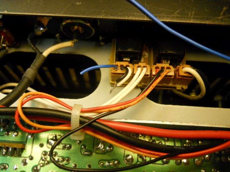
Here is a rear view of the PA/CB switch. The lower portion gets one foil trace leading to it cut. The lower-right two switch pins get a solder bridge across them. The top section has three wires that lead to the PA and External speaker jacks on the rear panel. We'll cut the black and white leads at the rear panel near the jack and splice them together. This selects the "Ext" speaker jack all the time and shuts off the "PA" jack. And yes, the external jack also feeds audio to the internal speaker.
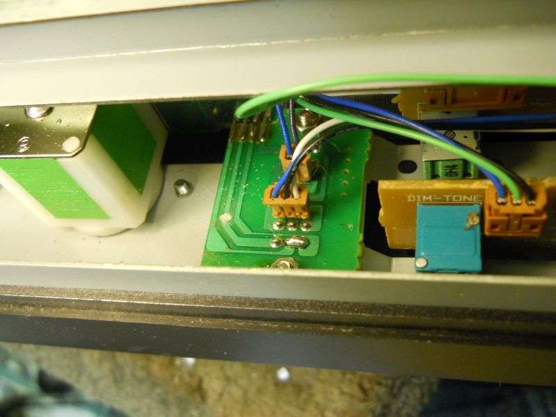
The gray wire, second from the rearmost on the channel-selector plug J33 gets cut. Black gets lap-spliced to one side of the cut. White wire to the other side. Blue wire won't be used, probably best to cut it close to the plug behind the PA switch.
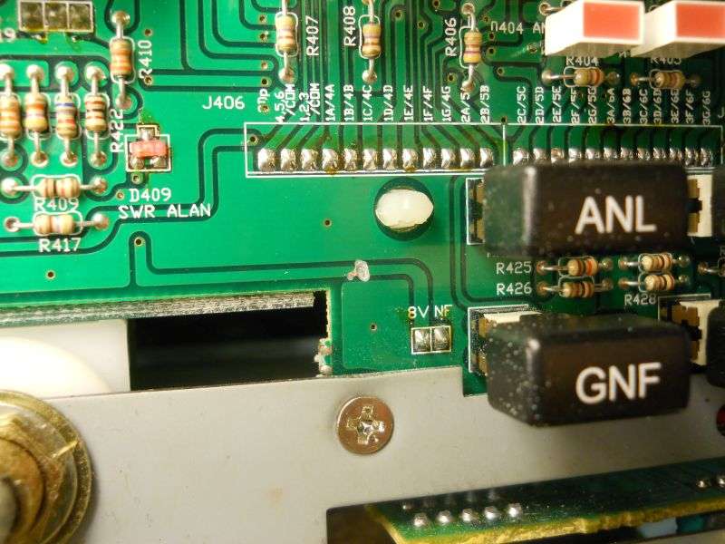
This gets half the job done. We have switched the gray wire on and off, but the yellow wire on the channel-selector plug J33 is next. The "GNF" button is a little more trouble to hijack. To start you'll need to remove the knobs and front panel. The circuit board where the switches attach is double sided and a foil trace on the front side of that circuit board will need to get severed.
This one, in fact:
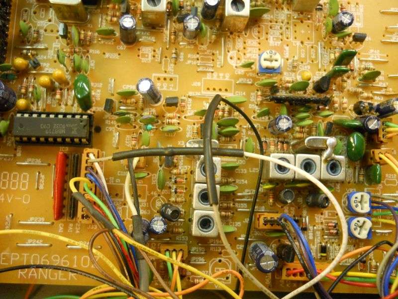
Next, find J413 immediately behind the GNF switch and follow the yellow and green wires over to the volume-control circuit board. Pull the yellow/green plug out of this board.
Now you'll find you have no receiver audio. A simple wire jumper will restore it. It's marked "JP502". A short piece of bare wire here will restore the receiver audio, and totally disable the GNF.
Yeah, I know there's no wire jumper in the pic. I got lazy and put it on the foil side. Didn't get a clear shot of that. Figure it out.
The only wire we need from the GNF plug at J413 is the green wire. Just lose the yellow wire. You'll need to splice additional length to the green wire so it can reach the channel-selector plug J33
We'll add a wire to the foil pad nearest J413. I had a devil of a time getting a clear shot showing that the yellow wire connects to that foil pad, and that one only. This is a new yellow wire. The original one from J413 is just too short. You don't have to use yellow for the new wire, I just thought it would clarify the setup to keep the color the same.
The lengthened green and the new yellow wire now go topside to the channel-selector plug J33. The yellow channel-selector wire gets cut, the yellow wire from the GNF switch to one side of the cut, the green wire to the other side.
This will make the PA button the "plus 64" function. Channel 1 starts at 27.605 and just goes up from there.
The GNF will be the "minus 32". Pushing it alone gets you lower channels. Pushing both gets you a "plus 32" that fills in between channel 40 and 60.
Bear in mind that I have transcribed this from an old text file, so there's always the risk of a typo. The pictures should reduce the risk of error. Proceed at your own risk.
73
Had a request that we do it with no holes added to the radio's exterior.
Okay.
What first comes to mind is the most-useless switch on the radio's front panel. The PA/CB switch. This one is not a big trick to hijack, and hot-wire the radio for CB mode only. The next-most useless button on the front would be the GNF. This guy said he would never miss that feature if it were disabled.
Here is a rear view of the PA/CB switch. The lower portion gets one foil trace leading to it cut. The lower-right two switch pins get a solder bridge across them. The top section has three wires that lead to the PA and External speaker jacks on the rear panel. We'll cut the black and white leads at the rear panel near the jack and splice them together. This selects the "Ext" speaker jack all the time and shuts off the "PA" jack. And yes, the external jack also feeds audio to the internal speaker.
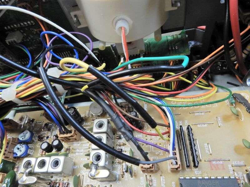
The gray wire, second from the rearmost on the channel-selector plug J33 gets cut. Black gets lap-spliced to one side of the cut. White wire to the other side. Blue wire won't be used, probably best to cut it close to the plug behind the PA switch.
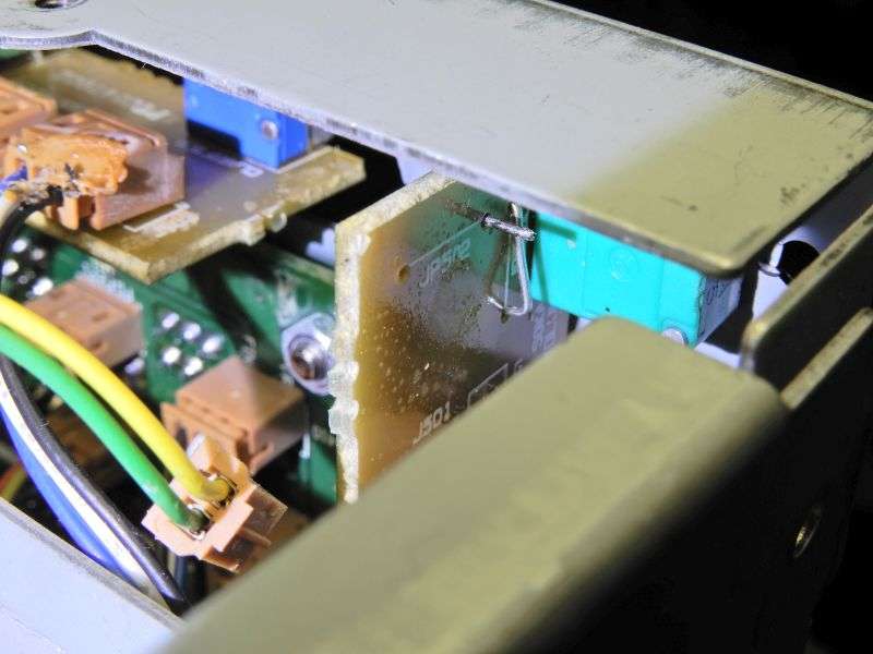
This gets half the job done. We have switched the gray wire on and off, but the yellow wire on the channel-selector plug J33 is next. The "GNF" button is a little more trouble to hijack. To start you'll need to remove the knobs and front panel. The circuit board where the switches attach is double sided and a foil trace on the front side of that circuit board will need to get severed.
This one, in fact:
Next, find J413 immediately behind the GNF switch and follow the yellow and green wires over to the volume-control circuit board. Pull the yellow/green plug out of this board.
Now you'll find you have no receiver audio. A simple wire jumper will restore it. It's marked "JP502". A short piece of bare wire here will restore the receiver audio, and totally disable the GNF.
Yeah, I know there's no wire jumper in the pic. I got lazy and put it on the foil side. Didn't get a clear shot of that. Figure it out.
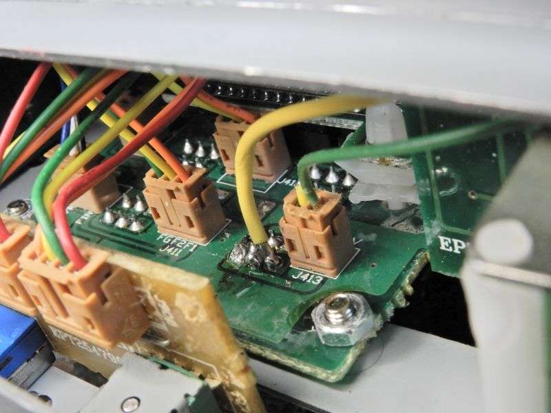
The only wire we need from the GNF plug at J413 is the green wire. Just lose the yellow wire. You'll need to splice additional length to the green wire so it can reach the channel-selector plug J33
We'll add a wire to the foil pad nearest J413. I had a devil of a time getting a clear shot showing that the yellow wire connects to that foil pad, and that one only. This is a new yellow wire. The original one from J413 is just too short. You don't have to use yellow for the new wire, I just thought it would clarify the setup to keep the color the same.
The lengthened green and the new yellow wire now go topside to the channel-selector plug J33. The yellow channel-selector wire gets cut, the yellow wire from the GNF switch to one side of the cut, the green wire to the other side.
This will make the PA button the "plus 64" function. Channel 1 starts at 27.605 and just goes up from there.
The GNF will be the "minus 32". Pushing it alone gets you lower channels. Pushing both gets you a "plus 32" that fills in between channel 40 and 60.
Bear in mind that I have transcribed this from an old text file, so there's always the risk of a typo. The pictures should reduce the risk of error. Proceed at your own risk.
73
Last edited:
