Want to mount inverted V dipolethe back of my house. Facing the town. Peak of my house is 14 or the 18 ft. Part , off the ground. the pitche I think is 5/12 ... I believe thats about 135°/\ shape when I measure it. 12 gage wire, 9ft. Per side. Made my own center connection. (Impressed myself).President Andy2 radio tuned to 5.5 watts. The insulated 9 ft. End wires will be velcro'ed every ft. Down the sides of the trim So I get no sag in wire. WILL THIS WORK my thoughts are since the waves are not coming from the tips, they're coming out from the V shape, so I'll be good forwards with sending a good broad band radiation out towards my town... but the rest of the radiation will be going directly into my house and I might get a little bit of reception in front my house but don't care about that direction. i should get great coverage going out the back, right? Or will the house itself screw my SWR ?....does that make any sense? I'm trying but hard to explain.this is confusing even after reading a sht load of stuff...Thanks to anyone that replied .

You are using an out of date browser. It may not display this or other websites correctly.
You should upgrade or use an alternative browser.
You should upgrade or use an alternative browser.
-
You can now help support WorldwideDX when you shop on Amazon at no additional cost to you! Simply follow this Shop on Amazon link first and a portion of any purchase is sent to WorldwideDX to help with site costs.
-
A Winner has been chosen for the 2026 July 4th Retevis RA89R Giveaway! Click Here to see who won!
1/2 wave Inverted V Dipole Antenna
- Thread starter Newbie solar guy
- Start date

Here's one good source of info on Inverted Vs. May answer some of your questions.
https://www.qsl.net/kk4obi/Center-fed V-dipoles Horizontal.html
If I understand your post correctly you intend to run your wires right up against the fascia boards. This will work but IMO you may experience a considerable amount of reflection and signal loss. If you can find a way to stand the wires off the boards or even above the roof a bit you will see better results. Your plan for an angle of 135⁰ should be just fine.
73 and good luck with your homebrewing.
Last edited:
Thank you for sharing with me. I'll hit up that site as well. Really appreciate this channel and the people here.helps beyond wordsHere's one good source of info on Inverted Vs. May answer some of your questions.
https://www.qsl.net/kk4obi/Center-fed V-dipoles Horizontal.html
If I understand your post correctly you intend to run your wires right up against the fascia boards. This will work but IMO you will experience a considerable amount of reflection and signal loss. If you can find a way to stand the wires off the boards or even above the roof a bit you will see better results. Your plan for an angle of 135⁰ should be just fine.
73 and good luck with your homebrewing.
I have rubber insolated 8in eye bolts coming. I'm in a hoa. That's the problem here.lol. as long as I can keep swr and heat low, I think we will be good.ill boost up from 10 to 15 watts. Maybe even go to 20w if my neighbors radios doesn't go nuts...lol they are like minded , good old boys! They will help me TEST how much I can go before I'm coming over their TV sets , radios , Netflix, a blender .hahahahHere's one good source of info on Inverted Vs. May answer some of your questions.
https://www.qsl.net/kk4obi/Center-fed V-dipoles Horizontal.html
If I understand your post correctly you intend to run your wires right up against the fascia boards. This will work but IMO you may experience a considerable amount of reflection and signal loss. If you can find a way to stand the wires off the boards or even above the roof a bit you will see better results. Your plan for an angle of 135⁰ should be just fine.
73 and good luck with your homebrewing.

I'm a Fan of the I-Vee antenna, for it's compact GoBag nature. I use 12AWG for open air suspension and potentially 1500W output.. Hardly need 12AWG for 5.5W. 5'/12' by my calculator is 113 degrees which in my book is quite good for directionality. My bug out rig is enabled for both 90 and 110 degree spreads. And you'll find 9' legs is too long.Want to mount inverted V dipolethe back of my house. Facing the town. Peak of my house is 14 or the 18 ft. Part , off the ground. the pitche I think is 5/12 ... I believe thats about 135°/\ shape when I measure it. 12 gage wire, 9ft. Per side. Made my own center connection. (Impressed myself).President Andy2 radio tuned to 5.5 watts. The insulated 9 ft. End wires will be velcro'ed every ft. Down the sides of the trim So I get no sag in wire. WILL THIS WORK my thoughts are since the waves are not coming from the tips, they're coming out from the V shape, so I'll be good forwards with sending a good broad band radiation out towards my town... but the rest of the radiation will be going directly into my house and I might get a little bit of reception in front my house but don't care about that direction. i should get great coverage going out the back, right? Or will the house itself screw my SWR ?....does that make any sense? I'm trying but hard to explain.this is confusing even after reading a sht load of stuff...Thanks to anyone that replied .

You make no mention of roofing material. No metal roofing
Last edited:
Thanks. Ya 9 ft is my start point I'm sure 8.6 will be around the final lenght. I'm using a coax choke instead of balun cuz I don't have any items to build that.im cheap.lol. clay roof.in Nevada. My biggest question is because the antenna is going to be mounted against the house, will radiate a signal? or should I use stand offs on the fascia boards with like, 6inch insulated standoffs screws with eye hole in them? Thanks for sharing your thoughts. Appreciate it.I'm a Fan of the I-Vee antenna, for it's compact GoBag nature. I use 12AWG for open air suspension and potentially 1500W output.. Hardly need 12AWG for 5.5W. 5'/12' by my calculator is 113 degrees which in my book is quite good for directionality. My bug out rig is enabled for both 90 and 110 degree spreads. And you'll find 9' legs is too long.
With the antenna apex at 18' and the ends of the legs close to 13' AGL you may find a 1:1 balun of value. A simple FT240-43 wound balun can be made nearly invisible from the street.
You make no mention of roofing material. No metal roofing
As said above, you're probably gonna have bad SWRs. All Dipole-based antennas along with verticals, want to be in "Free Space" with nothing around them within 1/4 wave .... which is your 9 Feet for 27mhz. You can try it and see what happens. All installations are different .... but I would expect problems. An alternative would be a Loop. Loops are current-point antennas and ignore nearby objects. You could run a Loop all around your house attached to the soffets/facia below the gutters in whatever shape you house is - square, rectangular etc .... Because this will be a considerable length beyond a full wave of 11 meters you should see some gain - and the antenna will operate on much lower bands if you are a ham. You will need a 4:1 Coaxial Balun and an Antenna Tuner for typical operation.
I will hope your I V as planned works for you.
I will hope your I V as planned works for you.
My current Inverted V is off the balcony of a condo and actually works quite well, in fact better than I expected. The open side faces a little North of East and allows me to work Europe, South America, Central America easily when 10 meters (and 11) is open. It's not the ideal situation but beats no antenna at all. Works well for local also, seems to be fairly omnidirectional. It's performance was improved quite a bit when I moved it a foot off of the balcony structure.

73
73
Nicely done. You didn't make mention of SWR issues?My current Inverted V is off the balcony of a condo and actually works quite well, in fact better than I expected. The open side faces a little North of East and allows me to work Europe, South America, Central America easily when 10 meters (and 11) is open. It's not the ideal situation but beats no antenna at all. Works well for local also, seems to be fairly omnidirectional. It's performance was improved quite a bit when I moved it a foot off of the balcony structure.
View attachment 60431
73
Nice antenna setup,was curious how the swr was on it??? Happy Labor day weekend!!My current Inverted V is off the balcony of a condo and actually works quite well, in fact better than I expected. The open side faces a little North of East and allows me to work Europe, South America, Central America easily when 10 meters (and 11) is open. It's not the ideal situation but beats no antenna at all. Works well for local also, seems to be fairly omnidirectional. It's performance was improved quite a bit when I moved it a foot off of the balcony structure.
View attachment 60431
73


PS: SWR is not everything that matters........................
Last edited:
Do you have trees on your postage property? A tree limb 18-23' AGL is fitting for a nearly invisible I-Vee antenna. I say 23' to accommodate the 5' vertical depth of the I-Vee; therefore, the entire antenna is 1/2λ AGL. Your choice of 20w will work splendidly for 16 AWG wire or up to 12 AWG I-Vee antenna. The only need for 12 AWG in the case of 25W output would be strength against storm winds.I have rubber insolated 8in eye bolts coming. I'm in a hoa. That's the problem here.lol. as long as I can keep swr and heat low, I think we will be good.ill boost up from 10 to 15 watts. Maybe even go to 20w if my neighbors radios doesn't go nuts...lol they are like minded , good old boys! They will help me TEST how much I can go before I'm coming over their TV sets , radios , Netflix, a blender .hahahah
Hang it from the limb using a small single pulley attached to end of throw line.
Though the pulley run a seconding line to raise and lower the antenna as needed.
A 90 or 106 degree I-Vee will be about 5' in the vertical height above your leg spreader. A 90d I-V will have a leg spread just shy of 12', while a 106d spread will be 13.18'. Leg spreader may be 1/2"D wooden dowel section with 1/2"I.D. pipe segment (copper) connectors. Or 1/2" camo painted PVC with single or multiple segment connectors. Use 550 paracord strung from ends of spreader to ground weights, I use repurposed brake rotors, to tether antenna against Colorado winds. The center fed coax dangles perpendicular to spreader center and affixed to spreader to insure no sag; also eliminates coax weight on connector.
A choke balun of the usual "Fugly" nature will be far more conspicuous than a 1:1
http://www.vk3bq.com/2014/09/24/11-current-balun/ current balun made in the manner shown. In the referenced build the author uses coax. Coax is not necessary. A 48" of repurposed extension cord is usable; just keep track of + and - strands; mark the ends.
Tested my I-Vee yesterday with and without the 1:1 balun with the leg ends < 10' AGL. Supposedly at this height the need is NIL.
Without: 1.5W dead key 1.05:1 swinging to 13W and 1.15:1.
With: 1:1, 1.5W swinging 13W.
I might add, the 1:1 balun is wound with 16 AWG magnet wire chassis rated for 100W continuous; at 13.7 VDC. I have been using it and modulating, very briefly, upwards of 1200W without smoking it.
Build a 1:1 balun with FT240-43 with dual strands at 7 wraps each direction. Mount within 3D printer made PETG frame having nearly the height of an
SO-239, with the length and width minimally necessary to frame the wound toroid, mounted SO-239, connectors to affix antenna legs, and a small eye-bolt to hang it with. 100mm L x 75mm W x 25mm H. Frame is open to the weather across the broadsides.
I don't believe you need concern yourself with RFI and the neighbor's radios with 25W of RF power. As I understand it, your coax is the radiating entity that emits the RFI that may cause interference. Your coax with a low or balance SWR should not cause a problem. A choke's purpose is to minimize if not eliminate any that may occur.
Last edited:
If you want to keep the RF in band and going in and out of the antenna use choke baluns like the post above from Alabama Buckeye said.
I have choke baluns at the antenna, the tower base, and in the shack.
There are some pictures http://trolinger.com/david/ame25/tower.html of the antennas and you can see the big coil at the 40 meter antenna. That is an air wound choke balun. The other two are ferrite core and much smaller.
Same on the 10 meter antenna. Balun at the antenna and in the shack. There is an SWR chart at the bottom of the page and I spent a couple of days to get the SWR that way. Choke BALUNs play a major role in your antenna system.
Now on the 30 meter antenna I used a bunch of ferrite beads slipped over a piece of coax (instead of the air core) and it seems to perform about the same as the 40 with the air core but I don't run power on 30 since it is limited to a couple hundred watts in the USA.
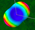
For general edification, radiation patterns of the dipole and the Inverted Vee:
The 180d dipole nearly spherical with NUL points at the element terminal ends. The maximum radiation pattern emulates a monster truck tire around its periphery, and decreasing across the sidewalls to the NUL axles.
The Inverted Vee increasingly diminishes the vertical dimension and emitted power while elongating the horizontal power reach and power, toward the horizon, and maximized as the 90d I-Vee is approached. The increasing horizontal reach is also accompanied by a narrowing of the horizontal breadth as 90d is approached.
The pattern changes from monster tire to what may be described as a loaf of French bread, with maximum power at the crunchy ends.
Attachments
Last edited:
Cleaned up a grungy connection I found, did a wire change and some trimming (shooting for 28.400) and ended up with this:View attachment 60438View attachment 60439View attachment 60440
PS: SWR is not everything that matters........................


Think I'll call it good.
 homebrewed 1:1 choke with a Fair-Rite 240-43.
Last edited:
dxChat
- No one is chatting at the moment.