
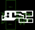
Figured I would share the photoresist mask I made for an oscillator. The 600dpi image fits 4 copies on a 4"x3" board. This was made for 1206 smd caps/resistors, JZ trimmers by Voltronics, HC49 crystals laid flat on board (because bigger crystals pull better than SMD ones) and sot-23 transistors. I think other sizes will fit. If your transistor pinout is different, you can flip the image.
There is a place for a second crystal in parallel for pulling purposes (or its pad can accomidate an inductor to ground). The trimmer has a pad next to it for adding more capacitance in parallel so a smaller range (easier to adjust) trimmer can be chosen. There are solder bridge points for connecting the other crystal pad so its capacitance is not present when not needed and another set of points to short out the trim cap to simulate max capacitance.
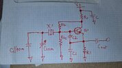
For fundamental oscillators between 1 and 30MHz, Rc is 470, Cout is 1nF, C supply is 10nF and C2 is 47pF. R1 and C1 are chosen to meet a few criteria, but the whole range can be covered very well with a few common pairs. For 1-4MHz, use 1.8k and 220pF, for 4-12MHz use 1k and 100pF, for 12-30MHz, use 560 and 47pF (good chance 1k and 100pF will run just about any crystal you have). Rb1 and Rb2 are chosen to establish an emitter voltage that places 1-3mA through R1, which also puts the oscillator in the active region and insures startup and stabilized bias. Their parallel equivalent resistance is across the crystal and loads it which can kill the oscillation alltogether if too low. Lower frequency crystals need higher bias resistances or they won't run. A good start is 12k for both Rb1 and Rb2, raised if needed at lower frequencies. Mid rail off the collector works fine for base voltage too. You'll end up between 1 and 3mA on an 8v regulated supply.
Just about any transistor will do. I just ordered the MMBT5088s, I expect they will work good for this (so would a 2222, 3904, 945 etc). RF stuff prefers thin film resistors and C0G capacitors. Tolerance doesn't really matter here, 5%, 20%, it don't really matter, so just meet the thin film and C0G critera and get the cheapest of those in the 1206 series.
Now I need to go find printer drivers for linux.
There is a place for a second crystal in parallel for pulling purposes (or its pad can accomidate an inductor to ground). The trimmer has a pad next to it for adding more capacitance in parallel so a smaller range (easier to adjust) trimmer can be chosen. There are solder bridge points for connecting the other crystal pad so its capacitance is not present when not needed and another set of points to short out the trim cap to simulate max capacitance.
For fundamental oscillators between 1 and 30MHz, Rc is 470, Cout is 1nF, C supply is 10nF and C2 is 47pF. R1 and C1 are chosen to meet a few criteria, but the whole range can be covered very well with a few common pairs. For 1-4MHz, use 1.8k and 220pF, for 4-12MHz use 1k and 100pF, for 12-30MHz, use 560 and 47pF (good chance 1k and 100pF will run just about any crystal you have). Rb1 and Rb2 are chosen to establish an emitter voltage that places 1-3mA through R1, which also puts the oscillator in the active region and insures startup and stabilized bias. Their parallel equivalent resistance is across the crystal and loads it which can kill the oscillation alltogether if too low. Lower frequency crystals need higher bias resistances or they won't run. A good start is 12k for both Rb1 and Rb2, raised if needed at lower frequencies. Mid rail off the collector works fine for base voltage too. You'll end up between 1 and 3mA on an 8v regulated supply.
Just about any transistor will do. I just ordered the MMBT5088s, I expect they will work good for this (so would a 2222, 3904, 945 etc). RF stuff prefers thin film resistors and C0G capacitors. Tolerance doesn't really matter here, 5%, 20%, it don't really matter, so just meet the thin film and C0G critera and get the cheapest of those in the 1206 series.
Now I need to go find printer drivers for linux.
Attachments

Last edited:


