• You can now help support WorldwideDX when you shop on Amazon at no additional cost to you! Simply follow this Shop on Amazon link first and a portion of any purchase is sent to WorldwideDX to help with site costs.
  • A Winner has been selected for the 2025 Radioddity Cyber Monday giveaway! Click Here to see who won!

Cobra 25gtl channel mod, help.

Cable Guy

Growth must be chosen again and again.
I Support WorldwideDX.com!
Dec 29, 2010
1,100
1,175
173
413-West Tennessee
Someone gave me a radio to fix. It had a dead reference xtal, no biggie. Board pc-417ac. Tc9106p pll. He said it had lower channels, switchable from the front. Well, it sure does, and without any xtal kit. I've never seen this mod and it's kinda confusing to me. Looking for any info.

Underneath 10.240 xtal. A track has been cut, a cap bridging it and wires from that to the switch.
IMG_20250517_174715806.jpg
Okay. When switched on, the gap and cap are bypassed. When off, an extra 33pf is added between xtal and circuit. I guess to pull the xtal, I got that

Then there is this...
IMG_20250517_174724235.jpg
IMG_20250517_174722259~2.jpg
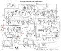
A transistor, some resistors and the switch.
IMG_20250518_135945300.jpg
IMG_20250518_135953110.jpg
R58 has been clipped. Could anyone try to explain this mod or link to it please? It was my understanding that this pll would require xtals and different mods to get the low channels. But this is proof that it can be done without that.
 

I think I have an understanding of what's going on here, but not well enough to explain it coherently. Not that I ever let that stop me.

The point of the transistor is to reverse the T/R signal going to the PLL. That's why R58 was clipped, to prevent the T/R signal from reaching the PLL along it's original path. The switch will either put the normal T/R signal through to the PLL (FCC 40 channels), or put it to the base of the transistor which will invert it (lower channels).

I think the 33pf cap is switched in on the lower channels to compensate for the fact that by default you'd be on a "zero" frequency. Why you'd be there has to do with the VCO putting out different frequencies on TX vs RX on any given channel and the fact that those frequencies are 450 kHz apart.

If this works the way I think it does, then when the mod is switched in and you're on channel 1 it should be 26.505 or 26.515 MHz depending on if the cap shifts the Xtal up or down.

If it does something else, well then I got it wrong. Not like it's the first time.
 
I think you're right. Thanks for that. I knew it did something to the trans/rec pin. I did notice that this radio, when low channels are selected, transmits/rec on the zeros in the lower frequencies. When in reg cb mode, it's on the nickels. I wanted to wrap my head around this before tackling that zero issue. I am plotting this mod on the schematic as that will help me understand better. I was told this was modded by an old school tech who went silent key some years ago out of KY. I bet he knew his stuff.
 
I think you're right. Thanks for that. I knew it did something to the trans/rec pin. I did notice that this radio, when low channels are selected, transmits/rec on the zeros in the lower frequencies. When in reg cb mode, it's on the nickels. I wanted to wrap my head around this before tackling that zero issue. I am plotting this mod on the schematic as that will help me understand better. I was told this was modded by an old school tech who went silent key some years ago out of KY. I bet he knew his stuff.
OK, I did get it at least somewhat wrong since it's on the zeros. The part I got right I'll give credit to Nomad for explaining a similar mod to the uPD2816 chassis in another thread.

And, yeah, that tech knew his stuff. It's a pretty clever mod.
 
  • Like
Reactions: Cable Guy
Well, I don't think it's supposed to be on the zeros. At least that's what the guy said. So you might be right anyways.
 
I don't think it's supposed to be on the zeros
That PLL chip does a frequency jump of 455 kHz when you transmit. Has one input pin connected to the radio's transmit-only voltage. This is to allow for the receiver's 455 kHz double-conversion frequency scheme.

That's forty-five and a half channels. The transistor in the pic is an inverter. Reverses the Tx input pin on the PLL so that it's low on transmit and high for receive. Reversing this transmit/receive frequency jump puts the radio below channel 1.

More than one hack using this trick includes a capacitor to load down the 10.24 crystal enough to drop the PLL 5 kHz, and get the radio back on the "fives".

73
 
  • Like
Reactions: Cable Guy
I got it now. The xtal I replaced with was not pulling well, had to change it again and a few caps to suit the new xtal. I might post it for those interested as I haven't seen it around. Thank you guys.
 
Okay, here is the modified schematic. I'd use a trimmer for the 33pf, as the new xtal only needed about 20pf, YMMV. I take no credit for this mod. Also, the brt/dim switch can be hacked for this mod.
 

Attachments

  • channel mod cobra_25gtl_sch.jpg
    channel mod cobra_25gtl_sch.jpg
    2.1 MB · Views: 24
Last edited:
  • Like
Reactions: TM86
That PLL chip does a frequency jump of 455 kHz when you transmit. Has one input pin connected to the radio's transmit-only voltage. This is to allow for the receiver's 455 kHz double-conversion frequency scheme.

That's forty-five and a half channels. The transistor in the pic is an inverter. Reverses the Tx input pin on the PLL so that it's low on transmit and high for receive. Reversing this transmit/receive frequency jump puts the radio below channel 1.

More than one hack using this trick includes a capacitor to load down the 10.24 crystal enough to drop the PLL 5 kHz, and get the radio back on the "fives".

73
There was a 29 ltd mod to get the lower channels like this as well I had one here a few years ago! A local guy here has it but I can't seem to get hands on it to copy it sure wish I could we all use 26.8150 and on a 40 watt 29 that would be awesome!
 

dxChat
Help Users
  • No one is chatting at the moment.