Yes you are right rixdafix that L30 wont affect the idle current which is BTW a static measurement. Please add your measurements into the schematic I made and then we will see. Sorry for changing the original schematic, but my intent is to just lift out the circuit of interest. Please let me know if I missed something or made a mistake in my drawings

You are using an out of date browser. It may not display this or other websites correctly.
You should upgrade or use an alternative browser.
You should upgrade or use an alternative browser.
-
You can now help support WorldwideDX when you shop on Amazon at no additional cost to you! Simply follow this Shop on Amazon link first and a portion of any purchase is sent to WorldwideDX to help with site costs.
-
The Father's Day Retevis RA89R Winner is Announced! Click Here for more info!
TRC-458, good receive, no transmit
- Thread starter rixdafix
- Start date
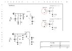
I hate to ask but is it possible you have cw and ccw reversed in the image?Yes you are right rixdafix that L30 wont affect the idle current which is BTW a static measurement. Please add your measurements into the schematic I made and then we will see. Sorry for changing the original schematic, but my intent is to just lift out the circuit of interest. Please let me know if I missed something or made a mistake in my drawings
Regardless, full clockwise is .607V, full ccw is .732V with a very linear adjustment through full travel so something is still amiss. This is with mic keyed and no audio input. Not sure if this is a clue but with the mic NOT keyed I see 3.4mV cw, 9.5mV ccw. I removed VR16 from this unit and my parts radio, both tested good, even smoother after I cleaned them. I've tried both VRs in circuit with similar results. For reference D51, R205, R219, VR16, C172, D66,67, C169, all check good.

I just assumed that increasing the quiescent current would be to turn the potentiometer CW, but you are probably right. Well ... to me this is very strange that you never get nearly 0 volts when the viper is at the end that effectively shorts the voltage to ground at R205 and it makes me think that something is wrong with viper ground (not fully open) which should show the behavior you wrote about.
What voltage do you have on the VR16 viper as well as D68 Anode?
What voltage do you have on the VR16 viper as well as D68 Anode?
Attachments
Off topic, and pardon my ignorance, but what software do you use to make these schematics?I just assumed that increasing the quiescent current would be to turn the potentiometer CW, but you are probably right. Well ... to me this is very strange that you never get nearly 0 volts when the viper is at the end that effectively shorts the voltage to ground at R205 and it makes me think that something is wrong with viper ground (not fully open) which should show the behavior you wrote about.
What voltage do you have on the VR16 viper as well as D68 Anode?
No problem Cable Guy! It is my first go-to software when I make simple schematics and I love it because how the symbols look like. It is a German software called sPlan 8.0 and you can buy it for only 49.9 Euro which would be about 50 to $55.Off topic, and pardon my ignorance, but what software do you use to make these schematics?


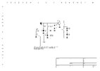
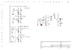
WOW!!  Quite confusing and sorry for D51 which is now corrected! It should be only a few millivolts on TR43 base when VR16 is fully CW and once again due to the fact that it puts R205 to DC ground. My schematics might as well be confusing but have a look at the different calculations I made and please do the ohm measurements - which should be close to 1 ohm - as in my schematic. Am I missing something guys?!
  I have fever so my brain may not do the work properly.
Quite confusing and sorry for D51 which is now corrected! It should be only a few millivolts on TR43 base when VR16 is fully CW and once again due to the fact that it puts R205 to DC ground. My schematics might as well be confusing but have a look at the different calculations I made and please do the ohm measurements - which should be close to 1 ohm - as in my schematic. Am I missing something guys?! I have fever so my brain may not do the work properly.Attachments
One ohm as measured in your schematic and thanks so much for taking time to make those. Here's another thing I noticed after rechecking driver bias. When I adjust VR15 for the driver bias as described using USB I can pretty much nail 40mA right on the money. However when I switch to AM and measure DC volts at base and collecter I get .72v and over 6v respectively. Only by lowering driver current can I get base voltage close, collector remains high. Also, when I unkey in AM, I have a lingering random voltage (1 to 2.5ish) on both collectors that slowly drops off over a minute or so. In sideband, collector voltage drops immediately after unkeying. All source voltages look good.
I'm gonna spend some time looking over this board real close. This was my first recap and I want to ensure I haven't introduced a problem. I've confirmed cap values and polarity three times. With the amount of soldering, I think I should scratch every bit of flux off in between the traces before continuing. I know the tiniest blob of solder can hide under there. I've already done that in the driver/final area but I'm going to go over the entire board. I also need to get a meter that can check caps down to pF.
Thanks again, Rick
Clean, clean like the dickens on the solder side of the board. That oatey flux is no joke and is very conductive and WILL cause problems, strange problems like lingering voltages, strange noises and instability. Please do that cleaning before anything else. Yes, oatey makes some nice shiny clean joints, but it will kill the radio. Use either 91% iso rubbing alcohol and a toothbrush and q tips, or make a 50/50 mixture of that alcohol and acetone. That mixture is great at cleaning old flux residue, just keep it on the board.
I'd recommend a rinse with deionized water and gentle hot air drying after the solvent wash. You will definitely need the iso or acetone to eat the rosin or whatever the goo is, but neither of those are particularly good at washing away conductive salts.Clean, clean like the dickens on the solder side of the board. That oatey flux is no joke and is very conductive and WILL cause problems, strange problems like lingering voltages, strange noises and instability. Please do that cleaning before anything else. Yes, oatey makes some nice shiny clean joints, but it will kill the radio. Use either 91% iso rubbing alcohol and a toothbrush and q tips, or make a 50/50 mixture of that alcohol and acetone. That mixture is great at cleaning old flux residue, just keep it on the board.
Back in my plumbers flux days, I remember seeing fine white glistening crystals growing my boards within a year or so after an acetone bath to remove salty flux.
depends on the flux i guess lol
Good point, I never used deionized water but distilled water and a dehydrator on low for a day or so. I will look into it for sure. I learned the hard way over 10 years ago when I was ignorant about flux. Now I use a quality electronic flux and no issues. I didn't think others had made my mistake with plumbers flux, and I chased my tail troubleshooting issues stemming from the wrong flux.
Just to clarify, I used rosin core electronics solder, decent stuff just can't remember the name. No plumber products touched this board. I just know a solder sucker can create splatters and I want to make sure none got mixed in to the old flux while it was bubbling. I've already found a couple of spots that made me say huh but nothing that had me powering it back up to test, not yet. I use a small pick to scratch off the flux between the traces in suspect areas and follow it up with a dry toothbrush.
Thanks y'all.
Thanks y'all.
Last edited:
I thought you were the one who used plumbers flux but looking back through the thread I see I am mistaken. Must have been another thread around here I was thinking of. Gosh getting old sucks.Just to clarify, I used rosin core electronics solder, decent stuff just can't remember the name. No plumber products touched this board. I just know a solder sucker can create splatters and I want to make sure none got mixed in to the old flux while it was bubbling. I've already found a couple of spots that made me say huh but nothing that had me powering it back up to test, not yet. I use a small pick to scratch off the flux between the traces in suspect areas and follow it up with a dry toothbrush.
Thanks y'all.
Don't mess with AM for this part. Setting bias is done in SSB with the mic gain down There is no need to switch to AM and check anything at this moment.When I adjust VR15 for the driver bias as described using USB I can pretty much nail 40mA right on the money. However when I switch to AM and measure DC volts at base and collecter I get .72v and over 6v respectively. Only by lowering driver current can I get base voltage close, collector remains high. Also, when I unkey in AM, I have a lingering random voltage (1 to 2.5ish) on both collectors that slowly drops off over a minute or so. In sideband, collector voltage drops immediately after unkeying. All source voltages look good.
Does D51 look different than D52? Maybe that MV1Y went bad and someone substituted it with a diode having a higher Vf. The Vf of a diode is current-dependent and can vary significantly when using different diodes. If you are unsure, compare D51's Vf to D52 (test them out of circuit, one leg lifted)
They look the same, just isolated and checked. .57 Vf on both and that varies with temperature change. By the way, I got rid of the lingering collector voltage by replacing the relay on a whim. Keyed was showing around 6.5v but when i unkeyed it would spike to over 16v and slowly bleed off. No idea. Contacts "look" good but relay coil only showed 80 ohms, parts radio relay showed 186 ohms. Are these relays still unobtanium? I'm wondering could C169 or C167 cause high current through TP2 if shorted? I haven't tested them yet.Don't mess with AM for this part. Setting bias is done in SSB with the mic gain down There is no need to switch to AM and check anything at this moment.
Does D51 look different than D52? Maybe that MV1Y went bad and someone substituted it with a diode having a higher Vf. The Vf of a diode is current-dependent and can vary significantly when using different diodes. If you are unsure, compare D51's Vf to D52 (test them out of circuit, one leg lifted)

Last edited:
dxChat
- No one is chatting at the moment.
-
-
-
dxBot:boog351 has left the room.
-
@ BJ radionut:
June VHF
The American Radio Relay League (ARRL) is the national association for amateur radio, connecting hams around the U.S. with news, information and resources.www.arrl.org
-