• You can now help support WorldwideDX when you shop on Amazon at no additional cost to you! Simply follow this Shop on Amazon link first and a portion of any purchase is sent to WorldwideDX to help with site costs.

Early Galaxy Saturn frequency counter problem

Spams24

Member
Oct 27, 2024
10
1
13
43
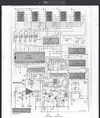
I have a Saturn on the bench that has several issues, but the frequency counter is the main one. It uses the EPT210010A board. All 2's are displayed as 6's. I have recapped, replaced the voltage regulator, and D603. Voltage is slightly low, 4.87v from D603. I have tested several other components, and cant figure it out. Any Ideas? Has anyone replaced this board with a different type?
 

To turn a "2" into a "6" the a segment has to be shut off when it should be on and the e segment turned on when it should be off.

All the later frequency displays wire the digits in an altogether different format from that one. Just not remotely compatible with the display wiring in a pre-1995 saturn. Having digit segments that light up when they should be dark is either a soldering fault that's bridging the 'e' segment of the digits to another segment's drive line, or a bad 5203 chip. They don't fail that often, but they do from time to time.

A more-common fault is segments that stay dark when they should be on. Tends to be caused by solder problems. An attempt to fix that fault could have bridged two adjacent foil pads together.

73
From the schematic, the best I can tell the digits are voltage relevant. Not like the newer individual segments that are powered separately. Am I thinking in the right direction?
 

Attachments

  • Screenshot 2026-03-04 at 20-00-39 galaxy_saturn manual.pdf.png
    Screenshot 2026-03-04 at 20-00-39 galaxy_saturn manual.pdf.png
    660.1 KB · Views: 4
The six digits are multiplexed. If you hold a fan between your eyes and the display, you'll see a strobe pulsation as the fan blades spin. Only one digit is powered at a time. The individual segments are all wired in parallel. The "a" segment of all six digits are wired together, and so on for the other six. The pin for each segment is the cathode of a LED. All eight (seven segs plus the decimal point) LED anodes tie to one common pin. When that pin on one digit at a time is powered, that digit lights. The 5032 chip has this scanning protocol built in. It allows you to drive six digits with 14 wires. But there's nothing steady you can measure with a meter. An oscilloscope will show you what's going on at each point in the circuit. A meter reading won't have any real meaning.

And the newer versions light up three digits at a time. Since they only flash from one set of three to the other, the scan frequency is lower. Radiates a lot less RF hash into surrounding circuitry. Takes a LOT more wires, though.

73
 
  • Like
Reactions: Gman
The six digits are multiplexed. If you hold a fan between your eyes and the display, you'll see a strobe pulsation as the fan blades spin. Only one digit is powered at a time. The individual segments are all wired in parallel. The "a" segment of all six digits are wired together, and so on for the other six. The pin for each segment is the cathode of a LED. All eight (seven segs plus the decimal point) LED anodes tie to one common pin. When that pin on one digit at a time is powered, that digit lights. The 5032 chip has this scanning protocol built in. It allows you to drive six digits with 14 wires. But there's nothing steady you can measure with a meter. An oscilloscope will show you what's going on at each point in the circuit. A meter reading won't have any real meaning.

And the newer versions light up three digits at a time. Since they only flash from one set of three to the other, the scan frequency is lower. Radiates a lot less RF hash into surrounding circuitry. Takes a LOT more wires, though.

73
Ok, Kinda makes sense. So how would one determine if the 5032 is the culprit? This is what Ive had trouble with. I do have a couple oscilloscopes.
 
From the schematic, the best I can tell the digits are voltage relevant. Not like the newer individual segments that are powered separately. Am I thinking in the right direction?

You need to find the data sheets, for as many of those IC chips on that board,
to be able to determine what is going where.
Once you know that, you can put the scope to work to find out if all of the pulses are moving along. It doesn't matter what it reads as long as you can follow the trail of pulses. One missing pulse means no display frequency reading.

Every time that pulse from the on-board-oscillator's clock ticks is like taking a picture of the radios frequency on the display, called strobing. (The fan trick that nomad wrote about.) BUT the board needs to see both the input frequency and the on board (strobing) clock frequency.

You need to find out where it stops and determine if there is a bad IC at that point.

Good luck. . . . .

73
 

dxChat
Help Users
  • No one is chatting at the moment.
  • @ heartbreaker3473:
    Hello gentlemen and Ladies. I have the dreaded RCI-2990 receive issue where my radio gets distorted when people get close to my location. I found the C90 Capacitor, but I can not for the life of me find the C89 capacitor. Can or does anyone have a picture of the exact location of C89 ? Thank you in advance, Wes
  • @ AudioShockwav:
    Wes, it's better if you start a thread on the main forum, more people are going to see your question.
  • @ heartbreaker3473:
    Okay, sorry, will put in a forum
  • @ heartbreaker3473:
    I put it in the general disscution help area and started a new thread. Thank you for letting me know.