
- Galaxy DX Models
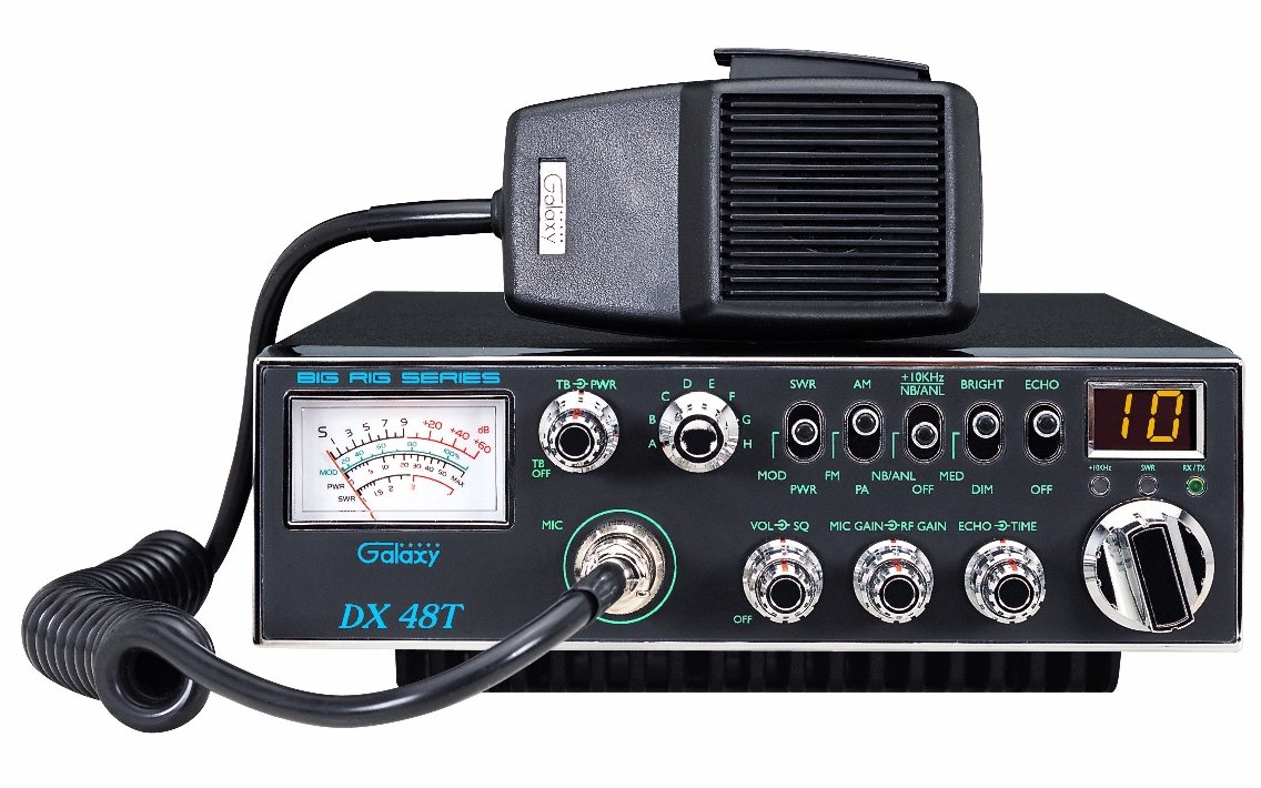
- DX48T
LINKS
RADIO MODIFICATIONS
- DX48T Frequency Conversion
- Channel Chart (After Modification)
- FC347 Frequency Counter Wiring Diagram to a DX48T
SEMICONDUCTOR INFORMATION
DIAGRAMS
- Block Diagram
- Schematic Diagram Main - Bipolar Chassis
- Schematic Diagram Main - MOSFET Chassis
- Echo PCB Schematic (EPT0SSB51J)
- RF Power Amp Schematic (EPA010011D)
- Control wiring
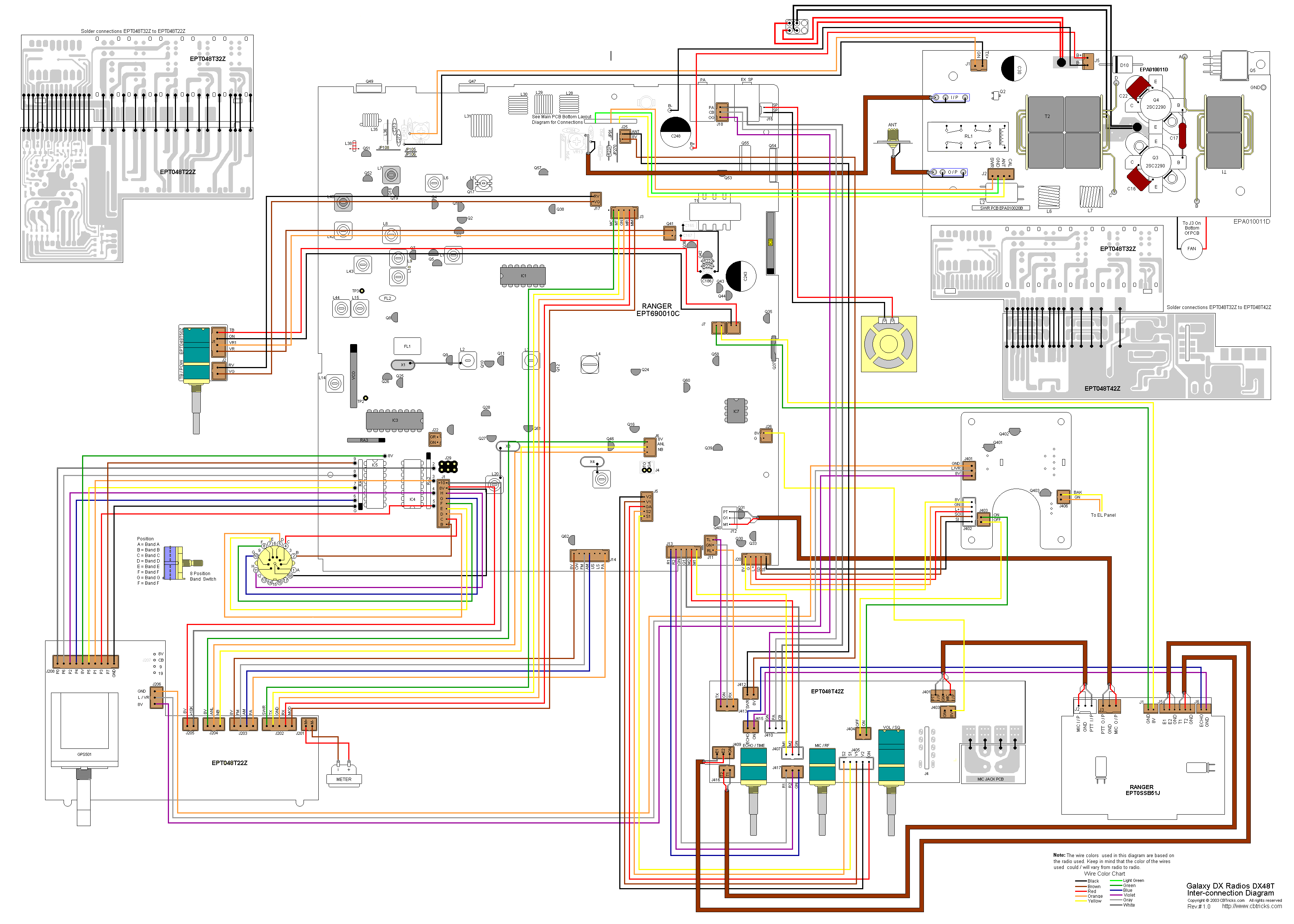
- DX48T Inter-connection Diagram
- DX48T Inter-connection Diagram
- Main PCB Layout (EPT690010C)
- VCO PCB (EPF000210Z)
- Dimmer PCB (EPT091V40A) Early Production
- Dimmer PCB (EPT091V41A) Current Production
- EL Driver PCB (EPT91V130Z)
- ECHO PCB (EPT0SSB51J)
- RF AMP PCB (EPA010011D) Early Production
- RF AMP PCB (EPA010012D) Current Production
- Amp Feed Back PCB (EPA010030Z)
- SWR PCB (EPA010020B)
- Channel Selector PCB (EPT48T20Z) Early Production
- Channel Selector PCB (EPT48T22Z) Current Production
- Display / Switch PCB (EPT048T31Z)
- Display / Switch PCB (EPT048T32Z) Later Production
- VR PCB (VOL / SQ, MIC / RF, ECHO / TIME) (EPT048T40Z) Early Production
- VR PCB (VOL / SQ, MIC / RF, ECHO / TIME) (EPT048T42Z) Current Production
- VR PCB (TALKBACK / POWER) (EPT048T50Z)
MIC WIRING
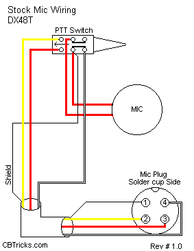
Stock
1- Shield (Ground)
2- Yellow (Audio)
3- Red (Transmit)
4- White (Receive)
Astatic (4 wire)
1- Shield
2- White
3- Red
4- Black
Astatic (6 wire)
1- Shield & Blue
2- White
3- Red
4- Black
Yellow NC
Daiwa EM-500
Cobra CA Series
1- Shield & Black
2- Red
3- White
4- Blue
Galaxy DC-521S (4 wire)
1- Shield
2- Yellow
3- Red
4- Black
Galaxy CB-660EI
1- Shield & Black
2- White
3- Red
4- Blue
Sadelta
1- Shield
2- White
3- Brown
4- Green
Turner
1- Shield & Red
2- White
3- Blue
4- Black
Yellow NC