When it goes to 210 watts, might be "carrier leakage" or your need just a simple tweak of one of the cans to reset the passband for your USB audio and not the Carrier or other IF stuff.
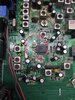
There's very little to view on the net over this - looks from the front like a TRS-485 - Dragon series Magnum 257 - small footprint, but to truly help you, we'll need a pic inside the board so we can compare it to the others that use this chassis.
There are "two" IF's used in this radio, one at 4.5MHz the other uses the typical 10.6975 one to "match up" to many other types of strips that use a simpler Mixer...
The problem lies in, you or it, makes a part change it's value, that 4.5MHz takes your signal a LOONG way off your course inside that radio.
Here's some "text" notes to help...advises you of the same thing I learned - DO NOT TOUCH that 4.5MHz area - for it will be extremely touchy and difficult to re-align once the Factory Pre-Set is lost.
Begin-----------------------------------8< SNIP AS NEEDED >8-------------------------
Magnum 257
Documentation Project
CBTricks.com
PLL Alignment
Caution: Do not touch the "4.5MHz Osc" by hand to prevent malfunction. In case malfunction make CON 401 short circuit after power off.
Set the Radio to adjust as below :
Vol on, clarifier center, RF gain max, SQ min, Mode AM, NB & SCAN off, Band A, Channel 1, Mic gain min, Power gain max, Echo delay min, AMT min, RB off Power on at 13.8V DC
1. DC power
a) Power on
b) Adjust T14 (ST 4304) so as DC Voltage on TP3 (R134) to be 1.2 Volt DC.
2. Put Freq. counter (lead) on TP2 (Q42. Collector) and then Adjust as below.
a) Adjust T17 so as frequency of VCO fin frequency to be 37.660MHz at channel 1 , E Band (26.965MHz)
b) Set the frequency of Radio 26.966MHz (use "STEP" button) and then adjust T18 so as VCO fin frequency to be 37.661 MHz.
c) Set the frequency of Radio 26.967MHz and then adjust T19 so as VCO fin freq. to be 37.662KHz.
d) Set the frequency of Radio 26.968MHz and then adjust T21 so as VCO fin freq. to be 37.663KHz.
e) Set the frequency of Radio 26.969MHz and then adjust T22 so as VCO fin freq. to be 37.664KHz.
3. Put the lead of frequency counter on TP4 (pin 7. IC3) at RX mode.
a) Adjust T24 so as freq. to be 10.6925 at LSB mode.
b) Adjust T26 so as freq. to be 10.6975 at USB mode.
c) Check if frequency is same as above in TX mode at both LSB and USB.
(Allowance must be 20Hz)
4. Fix T14 with parapin wax.
5. Adjust current of final Transistor at no modulation of SSB TX.
a) Put "+" lead of current meter on Pin 2 and "-" lead on Pin 1 of CON 1 and then adjust RV13 (1KB) for 70mA current.
b) Put "+" lead on Pin 4 and "-" lead on Pin 3 of CON 1 and make RV12 minimum (full counter clock wise) and then adjust RV11 (100ohm) for 60mA current.
Adjust RV12 for 120mA. (same "+" lead on Pin 4 and "-" lead on Pin 3)
c) Now current of C1969 collector should be 60mA.