• You can now help support WorldwideDX when you shop on Amazon at no additional cost to you! Simply follow this Shop on Amazon link first and a portion of any purchase is sent to WorldwideDX to help with site costs.

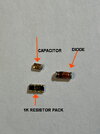
How to Identify these parts pictured

Techno1

Active Member
Feb 21, 2022
119
30
38
46
New Hampshire
So im working on a project and these parts I need some info on.

How to Identify the diode part # and size surface mount.
How to Identify the capacitor value and size surface mount.
The resistor pack is a 102+1k value, what size is the surface mount.

thanks for any info in Identifying these parts and sizethumbnail_IMG_8365.jpg
 

Look up an smt component size chart. You can find a printable version online and I know this because that's what I did. Aside from that there are some pretty good articles to research and get studied up.

When I started playing with smt a little while back I myself started from scratch in the smt world. I'm far from knowing it all but after some research I now know enough to get by.
 
the problem is the value of the cap and diode there are no markings.

the cap could be a common 104 cap
and the diode 1n4148 diode.

Just guessing LOL
 
The capacitor should have numbers but you'll have to scrape off that flux or masking to see it. That's where you'll need a magnifier to see.
The diode on the other hand, without a parts list or schemo as said above by others, it's a guessing game. You could probably figure it out with the right equipment but it would probably have to be a working diode in order to trace it.
 
To test the diode, use a 10k resistor in series with a 12-15v source to put current through the diode and see what the voltage is directly across the diode. Flip the diode around and repeat. Silicon junctions are around 0.6v, germanium junctions are around .3v. The resistor will limit the current so the diode don't burn up.

Silicon is typically used for signal switching and large signal rectification and germanium is used for small/weak signal detecting when it is beneficial to have it turn on at a lower voltage.

A regular diode will conduct one way (putting either 0.6v for silicon or 0.3v for germanium across the diode) and not conduct in the other direction (you will see the full supply voltage across it).

If it is a zener diode, you will see the silicon 0.6v drop in one direction and the zener voltage drop in the other (assuming it zeners lower than the supply voltage you are using).

As for testing the capacitor, depending on value, a simple DMM probably could tell you the capacitance. If it don't, there are other ways to measure it (like manually measuring its RC time constant with a known R, or resonant frequency with a known L). You could even put it in series with another capacitor of known value and measure the voltage divider at some AC frequency...
 
Last edited:
Just a thought I can plug in the module and check to see if its a zener by checking voltage on 1 side and then the other side. It could be a 5volt zener.
Module plugs into a 9volt circuit and powers a ic chip thats 5 volts .

So i will do that and if it is a 5volt zener great.

Just the cap is left to Identify, I checked the cap and no markings what so ever that I can see
 
The resistor pack is marked "102". You read this as if it were three color bands, brown black red. Should indicate 1000 ohms, or 1k.

Parts that are too small for proper ID markings just make the schematic that much more valuable. Trouble is that any product new enough to be built with surface-mount parts won't come with a schemo.

73
 
  • Like
Reactions: Enterprise312ok
The resistor pack is marked "102". You read this as if it were three color bands, brown black red. Should indicate 1000 ohms, or 1k.

Parts that are too small for proper ID markings just make the schematic that much more valuable. Trouble is that any product new enough to be built with surface-mount parts won't come with a schemo.

73
nomadradio

Yes I know the resistor pack is a 4x1k resistors.
the only thing i can think of is the cap is a coupling cap and value could be a 104/103 or even a 101. I will buy some or i can solder some regular caps and see what value will work in the circuit. Stinks there is no markings on the cap. There is enough to put a 1 digit alpha/numeric and they could code them that way a # on top and a letter on bottom, make life much easier.

Well thanks all for help/info and suggestions.
I will update when I finish the project and post if i find the cap value
 

dxChat
Help Users
  • No one is chatting at the moment.