• You can now help support WorldwideDX when you shop on Amazon at no additional cost to you! Simply follow this Shop on Amazon link first and a portion of any purchase is sent to WorldwideDX to help with site costs.
  • The Winners of the three Retevis radios 16 Anniversary giveaway are announced!! Click Here to find out if you won!

“60 Year Old Knight-Kit C-540 23-channel 6 tube CB plagued by Rx frequency jumps after Tx”

Jim55

New Member
Sep 25, 2026
6
1
3
74
Hello, I'm new here with an old radio. I am troubleshooting a 60-year-old Knight-Kit C-540 6 tube transceiver. It receives 23 channels, transmits on 1 (just have 1 crystal.) The radio now receives and transmits reasonably well, though it has seemed weak for many years, but I still have one persistent current problem: after transmitting, the receiver frequency suddenly shifts many channel positions on the dial. It does not depend on the length of transmission or speed or amount of button pushing.

This is not normal warm-up drift. The receiver can remain stable for quite a while, but pressing the microphone button and transmitting will cause the received channel position to jump (up or down on the dial.) The new position can then remain stable until the next Tx.

When properly adjusted, the channels can line up quite well. The problem is that transmitting causes an abrupt change in receiver frequency. I have not noticed any voltage changes happening at the time of the jump. It could be a brief event. The tuning capacitor & coils are not moving but do need to be physically moved to re-align the channels with the dial after a jump.

Some history that may be relevant:
The radio has worked as it should whenever used all these years until I turned it on in 2020 when the transmit-induced frequency shift along with a lot of static and popping suddenly appeared. It had not been mishandled in any way. I've replaced many old components on and off over the past 6 years and removed some of the noise. Some went away by itself. Tx and Rx remain weak.

The frequency change after TX is sudden rather than a gradual thermal drift. I don't see anything wrong with the mic contacts or wiring.

Multiple tube pin voltages are not correct, some very much so, but must be close enough because it mostly works.

I remember the audio output modulator,12AQ5, running very hot back in the '60's and it had to be replaced once long ago, it got weak. The current 12AQ5 tube seems weak now simply because it is not the obviously hottest tube in the set. It seems to be drawing far too little current. The audio preamp, 6AN8, and receiver oscillator mixer, 6CL8, seem to be drawing less current than expected also.

I also remember some capacitors (C-7 near the transmitter oscillator amplifier) causing much noise when objects were brought close to them. They are not doing that now.

A few years ago the static noise had an up and down pattern to it that happened by itself. This year the static was mostly uniform, you could say static, punctuated by loud popping sounds. Replacing many original filter caps got rid of a little static.

The bad static I had since 2020 went away recently after the radio was on for several hours. It wasn't anything I did, as far as I know. I wasn't even working on it at the time. Other types of noise have come and gone by themselves too.

I have another CB available as a signal source and normally transmit into a 50-ohm dummy load so I can use its leakage as a relatively weak reference signal.

At the moment the old radio actually sounds quite good and has relatively little unusual noise. The remaining major problem is this receiver-frequency jump caused by transmitting.

I would particularly appreciate opinions on whether this sounds more like:

>a receiver-oscillator component changing value when TX/RX voltages switch
>an intermittent contact in the TX/RX switching, (doubtful IMO)
>oscillator pulling through shared circuitry,
>a temperature-sensitive capacitor around L-4, (doubtful IMO)
>a problem with the L-4 coil or its slug, (doubtful IMO)
>weak tube(s),
>or something else typical of old tube CB sets.

I have the full original schematic,which can show any changes I made, and can post voltage measurements or close-up photographs of the transmitter/receiver oscillator areas (L-4/V-2) if useful. What I don't have is troubleshooting experience or any diagnostic equipment. I have 2 tranceivers and a multimeter.

Included is a schematic showing components I've replaced. I hope you can read it.

Thanks for your help. Jim55
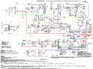
23 Channel CB Radio, Schematic 9-25-26.jpg
 
  • Like
Reactions: Naysayer

Love me a tube CB! I had a Lafayette for many years.
Did you use contact cleaner on the switch? Cleaning all contacts (switch, crystal socket+pins, etc.) is a great start.
Also, when you made the replacement PSU caps, did you add equalizing resistors acoss them? Unlikely to be part of your problem, but good design practise.
 
  • Like
Reactions: Lost Ram
I cleaned tube pin sockets and mic switch. The mic switch is enclosed so I can't see inside but it feels as smooth as always. The problems started as soon as I turned the radio on back in 2020. I didn't have any opportunity to key the mic.
I replaced many caps. I never heard of equalizing resistors across them. I don't have room anyway. I used what parts I had available so I often used multiple caps wired together to get the values and voltages I needed. They helped a bit. They are so close together I have insulator sheets in places to insure wires don't touch. I don't see any problems due to these caps, even as crowded as they are. Thanks
 
There's only one circuit that sets the receiver's frequency. No receive crystals at all, just the dial VFO. I count four 'black box' printed-circuit modules. Those were a real headache servicing TV and audio back in the 70s. If one part inside fails, you may have no way to test that one part. Like maybe the 100k resistor in PC1, maybe? That resistor gets the 200 Volt supply dumped across it when the mike is keyed. Should only dissipate about a half Watt into it when you transmit, but if it changes resistance value with temperature, this might do it. A marginal fault in V2 could do it, but that's the kind of failure a tube tester might not find. A substitute 6CL8 would be my next move. Keeping an eye on the DC voltage at pin 2 of V2A won't be practical. Test leads will disrupt that circuit if you probe that spot. Back in the day a VTVM, or vacuum tube voltmeter would have a 1 meg resistor inside the tip of the DC probe. Served to reduce how the probe would disrupt a circuit under test. Modern meters have a single unshielded wire connected to the probe tip. Not a good choice to poke into a sensitive RF circuit.

But that's where I would look, the resistor inside PC1 and V2.

73
 
  • Like
Reactions: brandon7861
I'll try to watch for temperature changes on PC-1 and monitor the 100K resistor. I had to build one of these encapsulated PC's from scratch in the past. There isn't much inside PC-1 so I can do that if I have to. Thanks for giving me a new place to look.
 
1790978915171.png
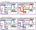
I know it says "power through mic, not shield ground", but how else would the green trace go low in TX? That green trace (which connects to red) that switches the TX (and audio amp) cathodes and the RX oscillator plate needs ground in TX, and in the original schematic, neither way provides it.
 
Last edited:
View attachment 77913
I know it says "power through mic, not shield ground", but how else would the green trace go low in TX? That green trace (which connects to red) that switches the TX (and audio amp) cathodes and the RX oscillator plate needs ground in TX, and in the original schematic, neither way provides it.
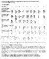
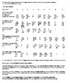
I tried to measure PC-1 temp with a thermocouple but saw no change in Tx vs Rx. Here are measured values of the internal resistors: 100K = 86.5K; 68K = 60.6K and the 1K = 1.5K ohms. I don't have any answer for your question, but I'm attaching a table in which the instructions give the recommended voltages and I show my measured voltages. According to the instructions, V-2, pin 2, and V-5, pin 2, are supposed to be about 5V in Rx, I get 43-45 V, and zero V during Tx. My measurements are in the ballpark. As far as I can tell it's doing what it should. How is another question.

I just noticed the mic switch contacts you posted in the bottom right picture are different from their positions in the original schematic. In the 3 correct pictures, the upper mic contacts are drawn in a "Y" configuration. In your bottom right picture, the contacts are in a "V" configuration and in both bottom pictures the left-most contact for the top "Y" connections inside the mic is missing. I think this is what is throwing you off. The way you show it, at the bottom right, the power from the red wire at the bottom goes through the mic and simultaneously gets shorted to gnd by the vertical contact in the "V" shape.; If drawn the right way, the top contacts are not contacting anything so power comes in from the red wire, goes through the mic and on to Pin 2 on V-5A. Only the cable shield is grounded. The mic has been working fine for 60 yrs. The connections are solid. It is still wired the way I did it in the 60's. I have not changed it. It does not appear to have anything to do with the static or frequency jumping.
 

Attachments

  • Historical data.jpg
    Historical data.jpg
    90.5 KB · Views: 2
I'll try to watch for temperature changes on PC-1 and monitor the 100K resistor. I had to build one of these encapsulated PC's from scratch in the past. There isn't much inside PC-1 so I can do that if I have to. Thanks for giving me a new place to look.
I measured no increase in temperature for PC-1 with a thermocouple. Here are the measured values of the 3 internal resistors: 100K = 86.5K; 68K = 60.6K; 1K = 1.8K. I tried to monitor voltages as the mic was keyed and saw nothing strange.

I'll attach a table showing the mfgr's recommended tube pin voltages and what I measured. I also put it in my previous answer but I want people to know this is part of my data.

It also contains some historical data from last year. Why it is slightly different this year I don't know.
 

Attachments

  • Historical data.jpg
    Historical data.jpg
    90.5 KB · Views: 0
Last edited:
I just noticed the mic switch contacts you posted in the bottom right picture are different from their positions in the original schematic. In the 3 correct pictures, the upper mic contacts are drawn in a "Y" configuration. In your bottom right picture, the contacts are in a "V" configuration and in both bottom pictures the left-most contact for the top "Y" connections inside the mic is missing. I think this is what is throwing you off. The way you show it, at the bottom right, the power from the red wire at the bottom goes through the mic and simultaneously gets shorted to gnd by the vertical contact in the "V" shape.; If drawn the right way, the top contacts are not contacting anything so power comes in from the red wire, goes through the mic and on to Pin 2 on V-5A. Only the cable shield is grounded. The mic has been working fine for 60 yrs. The connections are solid. It is still wired the way I did it in the 60's. I have not changed it. It does not appear to have anything to do with the static or frequency jumping.
In the top Y switch, looking at the RX drawing, the wire leading from the common of the Y switch goes to the audio coax shield... Who draws a switch contact on top of a coax shield? And who fills in the circle of a switch contact? Nobody, because that is not a switch contact and that wire was never intended to be moved when the TX drawing was made.

Everyone seems in agreement that the TX tubes shut off during RX, and that is obviously because the 100k plate resistor (in PC-1) powering the RX tubes lifts the cathode from ground. But to turn off the RX oscillator and turn on the transmit tubes, that green-red trace needs to go low somehow. Nomad even mentions this resistor seeing the full 200v supply in TX, I'm just trying to understand where it gets that ground from.

Whoever wrote "power in" in the mic drawing, Id like that person to explain how there can be "power" (better yet, why there should be power) on that mic line when it connects to the same line that must go low to turn on the TX tubes and turn off the RX tube. Writing "power in" on that line in the mic TX drawing is contradictory to how the rest of the circuit behaves.

Edit to add. Look right next door to the mic drawings. That red trace also connects to the audio preamp. For the audio preamp to work, that lline MUST BE LOW, so please explain how there is "power in" during TX when the preamp itself requires ground on that line. You are talking about having all of the preamp elements at darn near the same potential here...
 
Last edited:
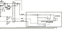
@ Brandon...I redrew the mic contacts at least 50 years ago. I didn't know details of how the circuit worked, I was just trying to show how the mic mechanism might look in Tx mode. In Rx everything is grounded and connected to black & shield. So I figured, apparently wrongly, that in Tx the power must be coming from the red wire. If the top connection to the shield is not supposed to move, the red wire is grounded and the mic still is too. It still looks to me like the mechanism would work, at least mechanically so I still don't understand this. Nobody has ever noticed this before. I'm including an original diagram of the mic contacts. I had to make some guesses about what moved & where since I can't see any contacts inside the mic switch. I admit I didn't do any analysis of where the power was coming from or going to. I never actually learned that much about circuit operation. This has just been a hobby I'm still learning. I'm sorry you got distracted by this, it's not the source of my noise. Thanks for spotting this decades old mistake. You are the only one to spot it.
 

Attachments

  • Mic.jpg
    Mic.jpg
    54.1 KB · Views: 2
Didn't mean to make a scene about it, thought the schematic above was original. I get hung up on little things, my apologies. Thanks for posting the original mic circuit as I couldn't find it.

I think nomads two suggestions are spot on.. I wouldn't just test the 100k though, I would replace it entirely. If it is changing resistance with temperature, it will change the operating conditions of the RX osc. tube and therefore change RX frequency. Metal film might be more temp-stable here, idk.. If a new resistor don't work, a tube swap as nomad suggested would be the next logical step. There really isn't much else to blame.
 
Last edited:
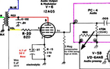
I am also a little curious about that 3Meg resistor. If I am interpreting your notes correctly, this was added to compensate for the 470k being too high.
1791225793601.png
Earlier you commented about this tube running hot and that it may now be weak. If you replace this tube, you might want to remove the 3Meg resistor and increase the 470k even further.

By raising this 470k resistance, the accumulated grid charge dissipates slower and this drives the grid bias voltage a little more negative which should cut the tube current down. I am not a hands-on tube guy, but I think a higher resistor value should equal a cooler tube, and adding that 3Meg in parallel to the other grid leak resistor does the opposite.

edit: AI says the proper way to reduce dissipation without messing up the operating point is to increase the plate resistance, not the gate resistance. So maybe my suggestion of raising that 470k is not so good from an audio fidelity standpoint. But it still remains that lowering it will make it run hotter.
 
Last edited:

dxChat
Help Users
  • No one is chatting at the moment.