• You can now help support WorldwideDX when you shop on Amazon at no additional cost to you! Simply follow this Shop on Amazon link first and a portion of any purchase is sent to WorldwideDX to help with site costs.

100 feet of RG-58A/U SWR effects shown visually.

You should have tried cutting to an exact multiple of 1/2 wavelengths so it would repeat the load impedance at the TX end. Any impedance coax can be used that way but it tends to narrow the bandwidth a bit. Hams have used 75 ohm CATV trunk line like that for years in order to obtain a good match with low loss on VHF/UHF. Of course that would have meant a lot of cut and try unless you used an analyzer. Better off to have bought the new cable.
but at least it could have been a work around if in a crisis.
As previously mentioned, it wasn't my coax and I didn't measure it, the discussion took place in cyberspace, just like this one ;)

As for the 1/2WL section I know this and discuss this in another thread, but would you want to use the coax, given that it was copper plated steel and producing sporadic readings, I'd rather not buy it in the first place, and I'd certainly not use it to feed anything other than rats :laugh:
 
Question: If line length does not affect SWR when the load is not a pure 50 ohms then why can we use a specific length of cable to create a transmission line impedance transformer?

I don't know that I have seen this answered to my satisfaction, so I will take a stab at it with a quote.

ARRL Antenna Book said:
It is important to note that in a lossless transmission line, SWR does not change with the length of the line or along the line. While the values of voltage and current do change along the line, the ratio of their maximum and minimum values does not.

The impedance transformer is calculated based on the length of the waveform while SWR is calculated by the ratio that exists at any given point within the waveform.


The DB
 
  • Like
Reactions: 1 person
It sure is a good thing that we common folks from the back waters of America, and other places distant and near, do not rely on knowing what the highbrows of radio are talking about in order to get our rigs set up and our waveforms on the air. It's getting so that operating a simple CB can give a fellow an inferiority complex faster than the prettiest girl in school asking him which acne medicine he uses . . .

Oh for the simple days of "can you still hear me?" ;)
 
  • Like
Reactions: 1 person
FWIW
I've found that the 'highbrow' and 'lowbrow' thingy is merely how an individual handles surprises. It's almost like those 'highbrows' are anticipating a shock of some kind, and them 'lowbrows' are dreading one. Or maybe the 'highbrows' are thinking, "I don't remember doing that before".. or "Why did I do that again?". You think?
- 'Doc
 
  • Like
Reactions: 1 person
scenerio #1
100 watt xmitter thru (lossless) coax into a meter @ the 50 ohm load,... what is the VSWR? 100 watts load input divided by 100 watts radiated = 1/1 = VSWR 1.0:1

In this scenario you specify 100 watts thru (lossless) coax into a meter with the 50 ohm load immediatly after the meter; And since the load matches the transmission line there is no reflected power so you are correct, the VSWR is 1.0:1.

scenerio #2 same 100 watt xmitter thru coax with (say) 25 watts loss into a meter@ the same 50 ohm load. what is the VSWR? 75 watts load input divided by 75 watts radiated = 1/1= 1.0: VSWR

In this one you indicate that we now have a 'real word' coax that has loss and show again the correct answer.

100 watt xmitter thru a meter and then thru coax with (say) a 25 watt loss into the same 50 ohm load= 100 watts xmiter output divided by 75 watts radiated = 100/75 = 1.33:1 VSWR.

Now in this one you have real coax and you have finally put the swr meter where it should be. ( I don't know why you insist on putting the swr meter where the antenna tuner should be )
But in this case your answer is wrong.
50 ohm coax and 50 ohm load is a matched condition and there will be no reflected power and the VSWR will be 1.0:1.
You are using transmitter power to the ratio of the radiated power to calculate VSWR and that is incorrect.
That is not the way it is done.
You are trying to use coax loss to create VSWR.
Transmission line loss does not create VSWR.
You appear to be disagreeing with your own logic.


huh??? do you have a reading comprehension issue? did you MISS this part where I said :

"your MISTAKE is that you put your meter in the WRONG place (at the transmitter) so you get these INCORRECT numbers"

you read something incorrectly and then try to tell me that I am incorret


but , thank you for AGREEING with my ORIGIONAL statement that,.....

transmission line does NOT create VSWR
 
Originally Posted by Reflections, by M. Walter Maxwell
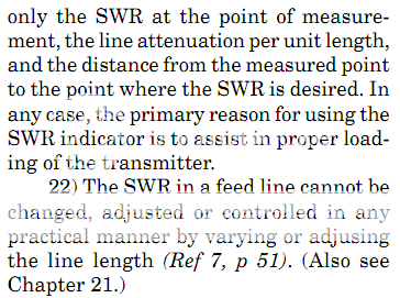
21)...22) SWR in a feed line cannot be adjusted or controlled in any practical manner by varying the line length (ref. 7, p. 51).


sooooooo, WHY do you keep insisting that coax lenght affects VSWR???
 
No I wouldn't want to use it either and was just waiting to see the response after the other thread. :tongue:

I wouldn't use it either, I have no idea of the loss thru copper clad steel, but,....

at radio frequencies BELOW VHF, almost all the loss in a transmission line is due to "copper" loss (I squared R loss).
 
OK, I want to jump in again on this for a minute. I have to admit to using improper terminology in this thread and suspect others may have been thinking along the same lines as I was. Working 12 hour night shifts and trying to think straight is not mutually conducive. We have come to equate impedance mismatches with SWR. 100 ohms = SWR of 2:1 etc. (or 25 ohms as well) I previously stated that SWR varies along a line terminated in a load that is different than the impedance of the transmission line. As others have stated, SWR does NOT change HOWEVER the IMPEDANCE along that line DOES change. At first glance it appears impossible to have a change in impedance but not a change in SWR until one digs deeper into the theory. My referencing the use of 1/2 wave multiples to accurately determine the "SWR" should have stated "impedance" instead. I have not tuned an antenna by "SWR" meters for the last 10 years or more while erecting them and use an antenna analyzer to tune for the proper "impedance" instead while attempting to reduce any reactance to as close to zero as possible. Knowing the impedance as well as the reactance can allow for quicker tuning as you can readily determine what needs to be done to effect a better match. This is the reason to use the 1/2 wave transmission line so that the true IMPEDANCE is repeated at the TX end not so that the true SWR is indicated at the TX.

I am now enjoying my four days off and have actually slept. It is amazing what sleep does for comprehension. That's my story and I'm sticking too it. ;)
 
  • Like
Reactions: 2 people
100 watt xmitter thru a meter and then thru coax with (say) a 25 watt loss into the same 50 ohm load= 100 watts xmiter output divided by 75 watts radiated = 100/75 = 1.33:1 VSWR.:thumbdown:

I guess I missed this my first time through. This line does not make sense as SWR is not about how much power has been lost between the meter and the load, but about the mismatch between the feedline and the load. Any 50 ohm feedline that is attached to a perfectly matched 50 ohm load will always show 1:1 SWR no matter how much loss is in the coax. If you don't get a 1:1 reading in such a case either you load isn't R=50 X=0, you have an issue with your coax, or something on the line is throwing off the readings.

All the effects of losses in a coax will do is make a higher SWR appear to be lower than it is, therefore your claim of this scenerio having a 1.33:1 SWR cannot be true as long as the coax and load are the same, and all of the equipment in question is working as it should.

"your MISTAKE is that you put your meter in the WRONG place (at the transmitter) so you get these INCORRECT numbers"

I personally tend to agree with the concept of putting it at the load end if possible, however, if the coax isn't long enough to have significant losses there will be minimal differences at best. Or if you know how much loss is in the coax, with a little bit of math you can work out what the SWR actually is from the readings present anywhere on the coax. Therefore, having the requirement of having the SWR meter at the load end is not a must, and is rarely used as it is typically impractical in reality.


The DB
 
you misread what others are saying and post snipets of an article that suits your purpose while ignoring the the parts that say you are wrong,

nobody said coax or loss in coax creates vswr that's you not reading too well,

you said
once again,.... the meter is in the wrong place

you also said
... and the reason is that you don't know where to place a meter in the transmission line!

your MISTAKE is that you put your meter in the WRONG place (at the transmitter) so you get these INCORRECT numbers:

once AGAIN, transmission line loss has NOTHING to do with VSWR!
the "load" doesn't "know" or "care" what "loss" is before it.

if you don't measure at the load INPUT (or a 1/2wl mult), then you are wrong!


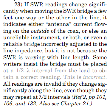
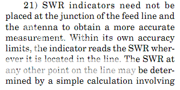
lets take a look at what the article you posted your snippet from really says

waltmaxwell.png

walt.png

walt2.png


loss in a transmission-line has everything to do with vswr at any point in the line, your 1/2wave multiples do not.
 
you misread what others are saying...nobody said coax or loss in coax creates vswr

clearly your reading skills are sub par.

look at the FIRST post where he says QUOTE:"This shows the effects of coax on SWR "

and then he said QUOTE:" Less length and the effects will be lessened, more length and the effects will be greater."

... and in post #2 , I said that was wrong

you seem to like to quote a lot, have you ever really read the references?

Originally Posted by Reflections, by M. Walter Maxwell
21)...22) SWR in a feed line cannot be adjusted or controlled in any practical manner by varying the line length (ref. 7, p. 51).

sooooooo, WHY do you keep insisting that coax lenght affects VSWR???


I'm done with you,..... conversations with pieces of furniture are seldom productive
 
what DB said is perfectly true in the context of the effects of coax loss on swr reading, the longer the coax the bigger the loss the lower the reading at some distance from the load,
shorter lines with less loss will indicate a higher reading due to less loss,
that's all DB was demonstrating,

if you have currents flowing on the outside of the coax shield then coax length does effect load impedance and vswr,

you won't get it because you don't comprehend what you read, you jumped straight in with a the "HUH next you will be telling me" statement without understanding what DB was showing us with his aim plot,

you were wrong then and have been wrong throughout the thread,
you done because you are out of your depth talking technobull
the dunce cap looks sexy on you;)
 
Last edited:

dxChat
Help Users
  • No one is chatting at the moment.