• You can now help support WorldwideDX when you shop on Amazon at no additional cost to you! Simply follow this Shop on Amazon link first and a portion of any purchase is sent to WorldwideDX to help with site costs.

$100 Paid for Answers these Questions

NightThumper

South of Pittsburg
Nov 8, 2017
655
1,551
153
This is a serious proposition. I’m trying to expand my knowledge. The first person based on TIME/DATE STAMP who answers each of the following questions will be paid $100 via PayPal friends and family on the same day they respond. All questions must be answered and not haphazardly.

As you know I have fixed the FatBoy 4 pill amp by modifying the feedback circuit with 5% tolerance components and decreasing resistance. The end result is both input/output impedances were improved and the amplifier is working fine with no issues.

I request that I can ask ONE/A Single question following the answers.

Here are the questions for which I’m seeking answer but until now have received no response.
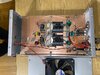
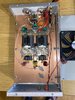
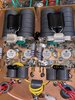
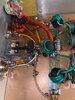
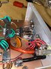
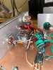
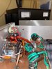
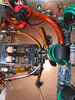
Pictures of amp are posted below.

1. What is the purpose of the orange (radial) capacitor going from ground to the relay?
2. What is the purpose of the mica capacitor going from ground to the relay?
3. What is the purpose of the disc capacitor going from one lead of the orange capacitor to one leg of the RF sensing transistor?
4. Then in all that mess there is a diode (I’m assuming a common variety) going from ground to the center leg of the RF sensing transistor?
5. On the opposite side there is a large orange disc capacitor going from ground to the relay.
6. What transistor is being utilized for RF sensing?
7. Should I upgrade the keying relay to something more stout?
8. I want to also install an RCA jack/or re-purpose the remote jack so I can manually key the amp and bypass the RF sensing when desired. Does this involve adding a second relay SPST to bypass? What type/rating relay is needed? Would like to still have the ability if possible to use a switch to go between keying jack or RF sensing.
9. What’s involved if I want to add bias/delay for SSB

PS: This is not a joke and not meant to insult anyone. I realize that a person should get compensated for their technical expertise.

Thanks in advance
Brad
KE0XS
South of Pittsburgh
 

Attachments

  • 10573F71-E1F4-4287-BF6F-87EED478A99D.jpeg
    10573F71-E1F4-4287-BF6F-87EED478A99D.jpeg
    1.9 MB · Views: 21
  • 5FE66BD7-B118-4587-A7DB-443BE37D5B71.jpeg
    5FE66BD7-B118-4587-A7DB-443BE37D5B71.jpeg
    1.9 MB · Views: 19
  • 08D4EAD7-E109-474E-9499-726AF8260045.jpeg
    08D4EAD7-E109-474E-9499-726AF8260045.jpeg
    2.2 MB · Views: 14
  • 06C352D7-350B-453F-B62A-C1E092FF171C.jpeg
    06C352D7-350B-453F-B62A-C1E092FF171C.jpeg
    2.2 MB · Views: 15
  • 498C07BC-7DD2-40D7-90C1-53E9DB2582C1.jpeg
    498C07BC-7DD2-40D7-90C1-53E9DB2582C1.jpeg
    1.5 MB · Views: 17
  • FAE5B91D-2719-4FFC-AC3C-8F131ED774EB.jpeg
    FAE5B91D-2719-4FFC-AC3C-8F131ED774EB.jpeg
    1.7 MB · Views: 14
  • A00DA657-BD9B-4813-8B4A-3F93A2768C79.jpeg
    A00DA657-BD9B-4813-8B4A-3F93A2768C79.jpeg
    1.4 MB · Views: 16
  • A9DCECC2-054D-484C-97C5-149FDD560D3C.jpeg
    A9DCECC2-054D-484C-97C5-149FDD560D3C.jpeg
    2 MB · Views: 15

If Answers were given, posted openly - how would you know they were correct?

I'm afraid to answer this (I do not need the money) - because I really would love to talk more about that Relay RF switch design back at the rear panel than to screw up this thread so badly that someone else whom would rather answer and get it right - but never gets the money...
 
Andy, in truth I wouldn’t know if each answer were correct. I’m not totally ignorant regarding the answers that would be posted. Maybe I’m naive but most of the folks here are good people. By posting on an open forum their answers would be subject to the scrutiny of other members. We have some very very knowledge people on this forum. In the back of my mind I’m hoping it’s one of those that responds…such as you. I pretty much read everyone of your post sir and you are truly an asset here. Your patience and diagrams/pics are excellent. I accept the fact technical people will have a difference of opinion to some degree about what exactly is going on. But right or wrong I’ll pay up as stated.

I’d love to hear your thoughts on the Relay RF switch design…it seems to me primitive/archaic but gets the job done. Venture in my friend with your answers then digress to talking about the design. I’m sure more than myself will benefit from the discussion.

If my Dad were alive he would know the answers to my questions, but he’s not. If I were back in Cedar Rapids Iowa where I was good friends with numerous Collin Rockwell RF design experts I would simply ask them. Instead I’m in PA and no longer have those types of associations.

Hopefully someone can use the money or simply enjoy a nice dinner on the town.

Brad
 
Last edited:
I’d love to hear your thoughts on the Relay RF switch design…it seems to me primitive/archaic but gets the job done. Venture in my friend with your answers then digress to talking about the design. I’m sure more than myself will benefit from the discussion.

Well, first if you came up with this idea, I admire your diligence in incorporating a unique feature I don't always see.

The Pic's you took provide some great resolution and detail, the one that started me down this rabbit hole was this...
upload_2021-7-16_17-24-30.png

I saw / see some details that many have asked about in general about why amps need to be tuned...

One of those issues - you have addressed here...
upload_2021-7-16_17-28-4.png

The "shorting jumper" allows The RF RX and if in bypass, TX out - and your application of the Mica cap tickled me silly because of what it does and the simplicity of the design hits the nail on the head for what could have been a major tuning "glitch" many see in their own "stock converted - yet to be tuned" - Amps - especially when run in bypass.

So you did your homework.
upload_2021-7-16_17-38-58.png
You may have given away some secrets of others that they may wind up taking to their Grave.​

But the utilization of the space you had to work with - you have done better than even some commercially made amp maker designs in addressing a tuning issue many don't see or recognize, that being the wire used to connect the COMMON Contact so the DPDT relay can alternate the poles of throw - you simply used a shorting jumper and the Mica cap to tune away an inductive event caused by the 2 connecting - Stranded - wires and the reactive effects from them when in RX or Bypass modes..

When an amp is off, Bypassed or in receive mode, that long run of wire is parasitic to the whole effort of having a tuned system. The effects of stray reactive components (The XL and XC) can wreak havoc with the amp and the radio tied to it - even if the amp does not have any power applied to it.

When it (the amp) is not needed - the run length internally in the amp - tends to generate an SWR "bump" sometimes it's enough of a bump to cause problems trying to bypass the amp so you don't destroy both your equipment and the other operators - in the process of using this in bypassed for short distance contacts.

For reference - look at the Red stripe wire, compare it to the wire INSIDE the Relay - the length of wire between both sides added together inside the relay is still LONGER than that Red-stripe wire! That's a long wire run in there many don't think about. And that length is not including those cladded spring contacts.

So in regards to the Amp design - I commend you to even partake in showing your work (or your techs')

 
Last edited:
Andy, I take no credit in anything regarding this amplifier. I purchased it from FatBoy and someone there either did the design or learned from someone else. I’m simply trying to understand what’s going on.
 
Last edited:
Just another view - self explanatory...

upload_2021-7-16_21-50-28.png

Using the Amps "Resting Default (N.C.)" The Shorting Jumper just does what it's for, then when the amp kicks in the Relay switches poles and changes the RF POWER terminal connecting it to Common ANT to send out the power - note the CAP used helps offset the impedance bump from the Combiner Relay Reactive components - the Shorting Jumper has it 's own.
.
Relay Schematic
upload_2021-7-16_21-52-18.png
Shown in N.C.
(Normally Closed)​
 
Last edited:
Instead of giving away money why didn't you just ask in pm a amp builder. There is a few here and pleanty on the net that am sure would take your money in a heartbeat
 
  • Like
Reactions: tecnicoloco
Andy, in truth I wouldn’t know if each answer were correct. I’m not totally ignorant regarding the answers that would be posted. Maybe I’m naive but most of the folks here are good people. By posting on an open forum their answers would be subject to the scrutiny of other members. We have some very very knowledge people on this forum. In the back of my mind I’m hoping it’s one of those that responds…such as you. I pretty much read everyone of your post sir and you are truly an asset here. Your patience and diagrams/pics are excellent. I accept the fact technical people will have a difference of opinion to some degree about what exactly is going on. But right or wrong I’ll pay up as stated.

I’d love to hear your thoughts on the Relay RF switch design…it seems to me primitive/archaic but gets the job done. Venture in my friend with your answers then digress to talking about the design. I’m sure more than myself will benefit from the discussion.

If my Dad were alive he would know the answers to my questions, but he’s not. If I were back in Cedar Rapids Iowa where I was good friends with numerous Collin Rockwell RF design experts I would simply ask them. Instead I’m in PA and no longer have those types of associations.

Hopefully someone can use the money or simply enjoy a nice dinner on the town.

Brad
Brad,
By posting the response here, you are giving away your expensive information. Thanks for letting us learn along with you, you are a good man.
Chris
 

dxChat
Help Users
  • No one is chatting at the moment.