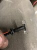
Hmm...Found something kinda interesting regarding the "Grain of wheat" lamps - their filament resistance when cold, plays a role in how much heat and the lifetime hours the lamp survives being cooped up in that housing with a grommet for a blanket.
If you know the voltage, being 8 volts, several types of bulbs than can play the role in replacement and in some cases will last as long, if not longer than, the radio it went in.
Don't be afraid to use a bigger bulb - same voltage, but you know you can unsolder the glass from the base, and you'll have a grain of corn, not wheat - size bulb if you need to replace the original with something - you just don't always have the SIZE to work with, so use something that the voltage and filament ratings are similar IF anything - a higher rated voltage (say 10 V rated) pay attention to the filaments resistance.
Most are 0.2 to as high a 1.15 ohms - the "voltage" part comes in as a current to resistance when the filament heats up. The higher the voltage, does not always equate to a higher lifetime rating - the filament takes in a specific current rating in amps - per volt - to light up. The circuit the bulb in a flashlight uses, works because the filament takes in current at a specific resistance rate and the current the batteries produce - stabilizes at a given point
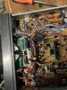
Yes, you may need to rewire the bulb to a spot on the main PCB to obtain 12 volts and route it thru a resistor to offset the intake current draw - the Grain of wheat in there was more for 6V and lasted as long as it did because of the filaments resistance was higher than most standard grain of wheat types.
Even the use of a "bi-pin" push in bulb can work, just use a dropping resistor of say, 10 ~22 ohms to help drop some of the voltage thru the resistor side before it hits the bulb - then you can use a simpler flashlight bulb to work where the grain of wheat was - just don't overdo it.
If you know the voltage, being 8 volts, several types of bulbs than can play the role in replacement and in some cases will last as long, if not longer than, the radio it went in.
Don't be afraid to use a bigger bulb - same voltage, but you know you can unsolder the glass from the base, and you'll have a grain of corn, not wheat - size bulb if you need to replace the original with something - you just don't always have the SIZE to work with, so use something that the voltage and filament ratings are similar IF anything - a higher rated voltage (say 10 V rated) pay attention to the filaments resistance.
Most are 0.2 to as high a 1.15 ohms - the "voltage" part comes in as a current to resistance when the filament heats up. The higher the voltage, does not always equate to a higher lifetime rating - the filament takes in a specific current rating in amps - per volt - to light up. The circuit the bulb in a flashlight uses, works because the filament takes in current at a specific resistance rate and the current the batteries produce - stabilizes at a given point
- it's why they use a Grain of wheat lamp, the current thru the filament is small because of the type of filament used is also light and very thin - even thinner than a typical flashlight bulb.
-

Yes, you may need to rewire the bulb to a spot on the main PCB to obtain 12 volts and route it thru a resistor to offset the intake current draw - the Grain of wheat in there was more for 6V and lasted as long as it did because of the filaments resistance was higher than most standard grain of wheat types.
Even the use of a "bi-pin" push in bulb can work, just use a dropping resistor of say, 10 ~22 ohms to help drop some of the voltage thru the resistor side before it hits the bulb - then you can use a simpler flashlight bulb to work where the grain of wheat was - just don't overdo it.