• You can now help support WorldwideDX when you shop on Amazon at no additional cost to you! Simply follow this Shop on Amazon link first and a portion of any purchase is sent to WorldwideDX to help with site costs.

5-pin DIN to 4-pin Cobra mic socket.

Cutlass327

Well-Known Member
May 1, 2016
309
212
53
NE Ohio
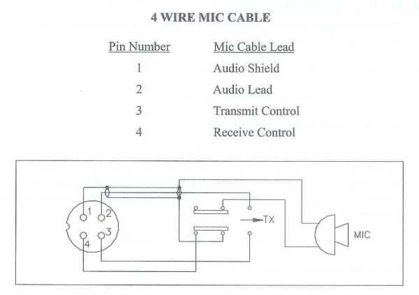
As the header say, I want to eliminate the 5-pin so I can use my regular mics on a TRC-465. Looking ar the back of the socket, there is a small board attached. Removing the socket, you can see pin number on the socket, and with the 5 pins arching over the top they are 3 5 2 4 1 and then the "housing" of the socket is also soldered to the board. I am guessing that pin is chassis ground, as it is screwed to the chassis.

Using this picture, I have the Shield on the 4-pin #1, White on Pin #2, Blue is tied to shield, as on the board the trace goes across 1 & 2 tying them together, and Black is to pin 4.

realistic_21-1172_hand_held_dynamic_microphone_cb_radio.gif


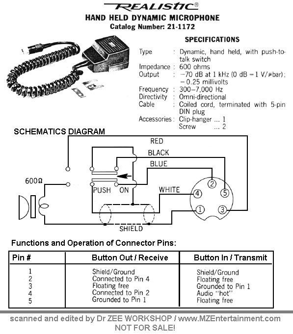
Now, My issue is when I key the mic, it switches to transmit, but it has a fog horn going out. Am I not wiring it correctly? I used this picture to compare and make connection.

galaxy-mic-wiring.jpg


The Blue wire just ties the audio feed to ground when in RX otherwise no change.

I will say, I also switched resistors R151 and R152 as mentioned in the last couple posts of this thread. Would that have anything to do with it? I used the 6.8K ohm value.
 

Ok, Cutlass, so you know, a little history...

Radios Shack produced their line using a SHORTING method to ground out their Mic Audio Line in the radio. They did this for several excuses, I can't say reasons - but they did prove their Receive effort and Urban Myth that they were certainly different.

You short the Wire that goes to Pin 2 of your 5-pin to Pin 1 on your Mics' 4-Pin. (To Some, they feel it's easier to remove it completely - but if you do, you lose a nice 5-wire Mic cord to replace another cord that is a 5-wire.) BUT THIS EXTRA WIRE HAS TO GO SOMEWHERE IN THE HANDSET - so it goes to SHIELD or COMMON in the DPDT Contact - UNUSED to BEING USED For ground - so Ground Pin 1 at PLUG, COMMON/SHIELD at DPDT Switch.

So the "fog horn" is the feedback from that...

Typical wiring for Cobra / Uniden - from the PLUG side...

4-pinPLUG.jpg
Now, 4 Pin - in Both PLUG and JACK - remember they are MIRROR images of each other...

4-pinIdentification.jpg

Now, Realistic, STILL USES 4-PIN WIRING back at the radio...

Yes, Get your head around this, it's Important that you do understand the logic of the noise abatement they did...

THE HANSET PIN 2 SHORTS TO PIN 4 OF THE HANDSET - when in RX.

So the 5-wires you have in the REALISTIC Handset - all 5 WIRES are USED!

In the Radio - they only use 4 - PINS of the Mic Socket . Like the Cobra and Uniden - so Wire the Handset to Short Pin 2-WIRE which isn't Audio (just extra) to Pin 1 in RX, They did this to keep down noise pickup - the wires act like antennas - and the radio simply picked it up and sent in thru the Receive audio side and made the radio sounds like a horrible noisy receiver- like all those others. So THEY PUT ALL 5 WIRES TO GO SOMEWHERE when the Radio was in RECEIVED mode - so it kept their Receivers quiet - but you have to figure out what wires were NOT needed. -

So to keep it simple - FOR 4 Pin...HANDSET...
  • you SOLDERED Pin 2 wire to Pin 1 of the PLUG end and COMMON ground at the Switch in the handset - this keeps the wire from acting like an antenna - it's constantly grounded...
For SOCKET...4 Pin...

UNIDEN Pin 1 GROUND
UNIDEN Pin 2 AUDIO - but you take from Pin 4 on REALISTIC side...
UNIDEN Pin 3 Transmit - But you Take from Pin 3 on REALISTIC side...
UNIDEN Pin 4 Receive - But you Take from Pin 5 on REALISTIC side...


The Wires From the REALISTIC schematic...5-pinREALISTICDIN.jpg
Read the above several times so you understand...and hope this can help you know the schematic you show, is correct - but its' NOT. Because the Radio could care less about the 5th wire, it only uses 4.But the radio was form another maker (a.k.a UNIDEN) so they used theirs and you have to figure out the differences...

A good way to think of this...

Realistic and All the Others kept Ground At PIN 1 - and Farthest Away was their Receive - their Pin 5.

Audio SHORTED Pin 2 - but you needed it in UNIDEN - But You Modulated on Pin 4 but Sent it TO Uniden (That short - just Tie your Pin 2 wire from Realistic the one you don't use - to Pin 1 at plug and at the CENTER COMMON (Shield) too. Else you get noise.) All wires have to go somewhere...

Everything else kinda fell into place AFTER that
 
Last edited:
Ok, Cutlass, so you know, a little history...

Radios Shack produced their line using a SHORTING method to ground out their Mic Audio Line in the radio. They did this for several excuses, I can't say reasons - but they did prove their Receive effort and Urban Myth that they were certainly different.

You short the Wire that goes to Pin 2 of your 5-pin to Pin 1 on your Mics' 4-Pin. (To Some, they feel it's easier to remove it completely - but if you do, you lose a nice 5-wire Mic cord to replace another cord that is a 5-wire.) BUT THIS EXTRA WIRE HAS TO GO SOMEWHERE IN THE HANDSET - so it goes to SHIELD or COMMON in the DPDT Contact - UNUSED to BEING USED For ground - so Ground Pin 1 at PLUG, COMMON/SHIELD at DPDT Switch.

So the "fog horn" is the feedback from that...

Typical wiring for Cobra / Uniden - from the PLUG side...
Now, 4 Pin - in Both PLUG and JACK - remember they are MIRROR images of each other...

View attachment 36504

Now, Realistic, STILL USES 4-PIN WIRING back at the radio...

Yes, Get your head around this, it's Important that you do understand the logic of the noise abatement they did...

THE HANSET PIN 2 SHORTS TO PIN 4 OF THE HANDSET - when in RX.

So the 5-wires you have in the REALISTIC Handset - all 5 WIRES are USED!

In the Radio - they only use 4 - PINS of the Mic Socket . Like the Cobra and Uniden - so Wire the Handset to Short Pin 2-WIRE which isn't Audio (just extra) to Pin 1 in RX, They did this to keep down noise pickup - the wires act like antennas - and the radio simply picked it up and sent in thru the Receive audio side and made the radio sounds like a horrible noisy receiver- like all those others. So THEY PUT ALL 5 WIRES TO GO SOMEWHERE when the Radio was in RECEIVED mode - so it kept their Receivers quiet - but you have to figure out what wires were NOT needed. -

So to keep it simple - FOR 4 Pin...HANDSET...
  • you SOLDERED Pin 2 wire to Pin 1 of the PLUG end and COMMON ground at the Switch in the handset - this keeps the wire from acting like an antenna - it's constantly grounded...
For SOCKET...4 Pin...

UNIDEN Pin 1 GROUND
UNIDEN Pin 2 AUDIO - but you take from Pin 4 on REALISTIC side...
UNIDEN Pin 3 Transmit - But you Take from Pin 3 on REALISTIC side...
UNIDEN Pin 4 Receive - But you Take from Pin 5 on REALISTIC side...


The Wires From the REALISTIC schematic...View attachment 36507
Read the above several times so you understand...and hope this can help you know the schematic you show, is correct - but its' NOT. Because the Radio could care less about the 5th wire, it only uses 4.But the radio was form another maker (a.k.a UNIDEN) so they used theirs and you have to figure out the differences...

A good way to think of this...

Realistic and All the Others kept Ground At PIN 1 - and Farthest Away was their Receive - their Pin 5.

Audio SHORTED Pin 2 - but you needed it in UNIDEN - But You Modulated on Pin 4 but Sent it TO Uniden (That short - just Tie your Pin 2 wire from Realistic the one you don't use - to Pin 1 at plug and at the CENTER COMMON (Shield) too. Else you get noise.) All wires have to go somewhere...

Everything else kinda fell into place AFTER that

Why do I feel as though I need a cigarette?
 
upload_2020-4-21_10-33-52.png
I will say, I also switched resistors R151 and R152 as mentioned in the last couple posts of this thread. Would that have anything to do with it? I used the 6.8K ohm value.

Well, it would have been easier to get the Mic socket thingy worked out first, then worked on the Audio tweaks...

But - best to revert back to original then correct it after the radio is working - then move forward.


Well, it would have been easier to get the Mic socket thingy worked out first, then worked on the Audio tweaks...

But - best to revert back to original then correct it after the radio is working - then move forward.
Yeah, i did my usual - too many things at once because "while I'm here, I might as well..."

When I soldered the wires to the 5 pin board, I just soldered 1 and 2 wires together and soldered them to the board in the corner where the "403" is. There was more room, less chance of accidentally shorting. On the 4 pin side, I just cut the 5th wire end off instead of trying to solder it on.
 
the only issue with those is the leverage. I want to eliminate the DIN plug due to its weakness in a mobile application, and so I am going to the Cobra 4 pin design to make all of my radios "universal fit".

As for my wiring...

I used a 5 conductor wire - red, white, yellow, black, shield.

I used yellow as "Blue".

I used shield as shield, obviously.

White as Audio

Red as TX

Black as RX

I then matched each color to corrosponding pin. Only variant is the yellow/shield, as yellow is not connected to 4 pin, and connected to shield at the board.

On the pics of the board Andy posted, the center trace with C401 and C402 is soldered to the housing of the DIN socket, screwed to chassis ground. I tried it not connected to anything, and then I connected it to chassis ground with a piece of wire, but nothing changed.

Adjusting the AM PWR trimmer did have minor affect..
 
You're getting "foghorn" still?

The case is "Positive or Negative Ground" so it's an insulated case - the outer shield ring that holds the plug in, is "crimped, and not connected" - just holds the wires from pulling out. The Crimp is on or should be on, the outer sleeve of the Mic cord tucked away in the Grommet. So no connection, just unto itself for the Ring. It's to Case ground your radios Shield ground in Foil Board Ground.

So if I have your layout right.

White - Audio - Pin 4
Shield - Ground - Pin 1
Black - Receive - Pin 2 - Because Mic Board SHORTS it to Pin 1
Red - Transmit - Pin 3
Blue - "Spare" - Pin 5

Ok, if the Above is ok with you - I drew up the below to help me help you...

Will Update as possible ... keep reading...

There is a special instruction for the Blue wire - this is if you decide to wire it this way - note Pin 5 - is not used. But that is "what shorts" together. per their instructions. So solder all the wires in the Mic Cord as shown

But what about "pin 5" at the Radio? Is it connected to anything? Yes, the HANDSET.

To help you simply that - do the above in the plunger - only if you use Blue - then mount the wire to the lug as shown above - and Solder SHORT across Black Terminal to Blue Terminal - so the radio in RX MODE shorts out Black and Blue and ELEMENT - When you TX - Element DISCONNECTS from BLUE and Shorts to AUDIO (White) - SHIELD then DICONNECTS from BLACK and Shorts to RED. Black and Blue are now open or should be open but both tied to ground at the Radio thru BLACK - Verify that wiring and you should be go to go.

If you want to keep it simpler - just Short Blue to Shield at both Plunger and at Jack ok? IT's a spare wire but needs to be grounded to keep out noise.

I had to show you "both ways" because older Realistic sets used a Relay for keying and Pin 2 shorted to ground internally at the radio so they too had a "spare functionless wire" except to short out the Audio pin in RX mode to reduce noise pickup from poor shielding in the Handset.

Element return is still to shield - needs to be - but Blue - Black and Element "hot" go together
 

Attachments

  • TRC-465MicWiringJack.png
    TRC-465MicWiringJack.png
    317.5 KB · Views: 44
Last edited:
  • Like
Reactions: kopcicle
Pin 4 on the cobra MIC cuts the receive audio when keyed. If it does not cut the receive then you will have a hot MIC and the receive speaker will be on too. On a Cobra this causes the fog horn you describe.

Except for your radio has these already connected by the trace on the board between pins 1 and 2. The radio must already have a way to deal with the speaker being on when the MIC is hot. Like the keying relay cuts the speaker out somewhere else?

So the question is: Did the radio work correctly before you started working on it?

I would be tempted to cut the trace between pins 1 and 2 and wire that part like the Cobra too.
 
Well, using Andy's diagram, I have black and blue switched. That may explain why it is doing it then, not disconnecting the RX. I'll have to look to see where I have it.

I had unsoldered the speaker from the wores of the radio to keep me from breaking something, and it was still disconnected when I tried it. I was using a bench radio to listen. I then reconnected it to test if it "told" me anything, and it operated fine except the noise. I was able to hear myself thru the "horn" on the bench radio.
 
  • Like
Reactions: Shadetree Mechanic
Ok can you set it back to "stock" to see if the Foghorn was due to the Mic change?

Take a look - do you have a wire from the Mic Jack running to the Front panel?
upload_2020-4-21_21-17-15.png

You should have a wire off of Mic Jack Pin 3 - its' your TX - that routes to the CB/PA switch - it's what mutes the Speaker - if it doesn't have a wire - that may be your problem...
TRC-465CBPAswitch.jpg
 

dxChat
Help Users
  • No one is chatting at the moment.
  • dxBot:
    Tucker442 has left the room.
  • @ BJ radionut:
    LIVE 10:00 AM EST :cool:
  • @ Charles Edwards:
    I'm looking for factory settings 1 through 59 for a AT 5555 n2 or AT500 M2 I only wrote down half the values feel like a idiot I need help will be appreciated