They say a journey of a thousand miles begins with one step.
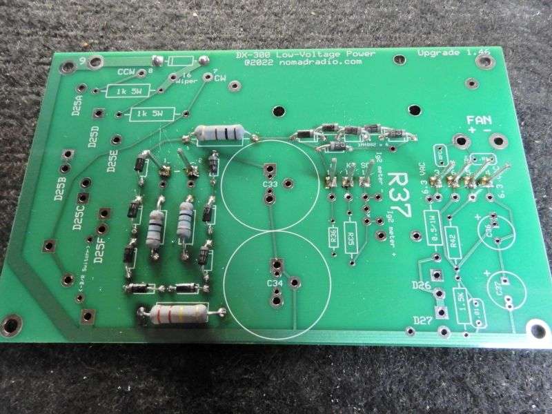
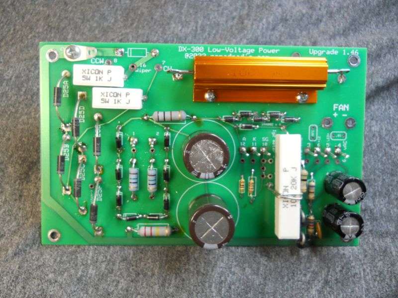
This board gets built in several steps. Parts count is 41 soldered-in components.
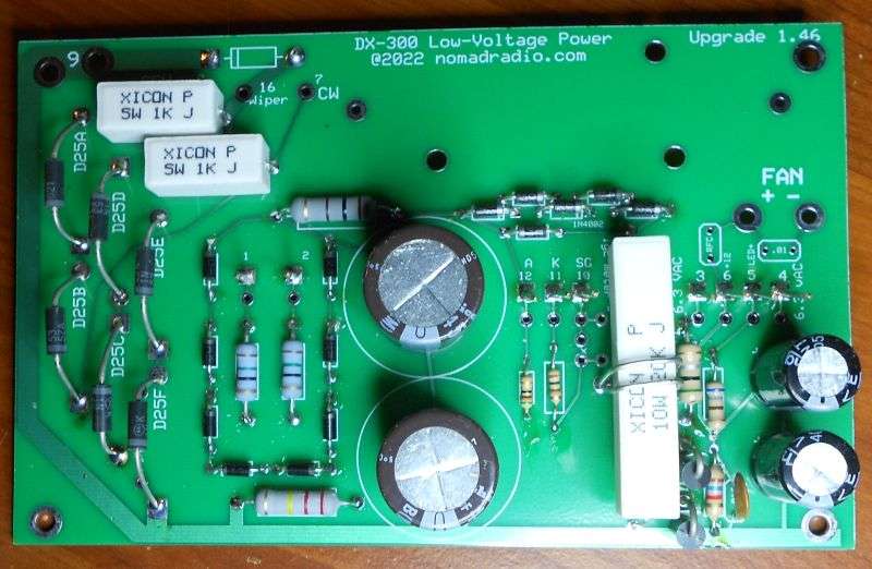
For those who missed it, we built and sell this circuit board to replace and upgrade the Pride DX300 base amplifier built in 1977 and '78. The FCC tightened the rule in 1979 for what is (and isn't) a legal ham amplifier to sell in the USA. The DX300 flunked the new specs and production ended forever.
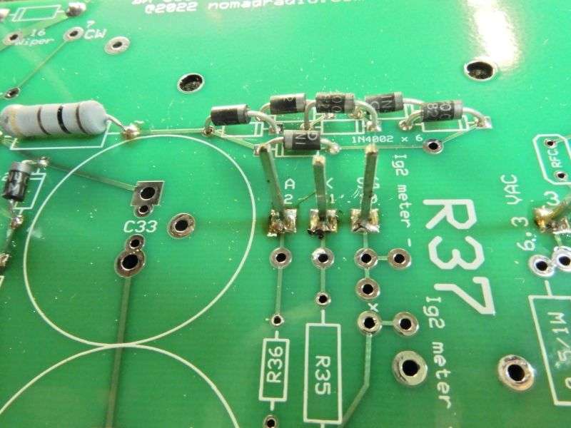
Starting point for assembly is these six 1N4002 rectifier diodes.

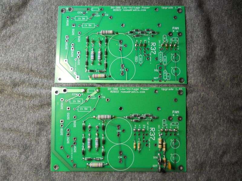
If this board were being wave-soldered, all the parts would get inserted before soldering the entire board at once.
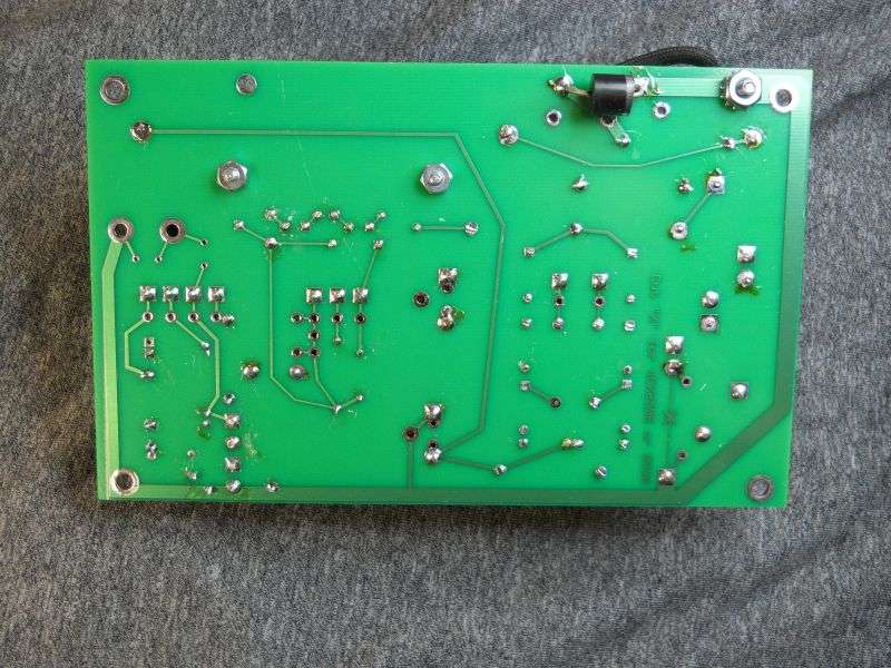
We don't have one of those machines. Every part gets hand soldered in the Pride power supply boards we sell. It's easier to navigate the dense forest of lead wires sticking out the solder side a half-dozen or dozen parts at a time.
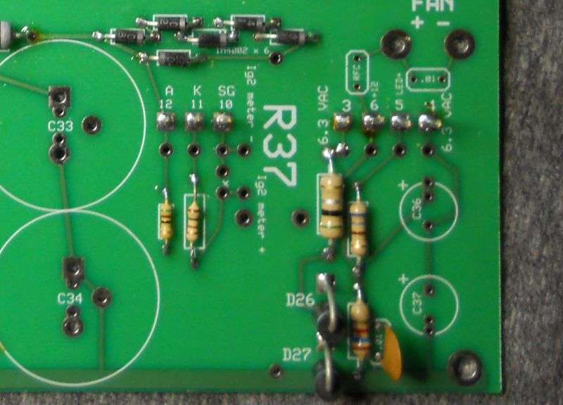
The next step after the six diodes above is the rectifier for screen and grid bias voltages.

Might or might not be more efficient to build these in several steps like this. It's a lot less stressful, seems like.
About those six diodes. You won't find them anywhere on the diagram for the factory's version of this board.

Sounds wasteful, but they serve one purpose only. They are in parallel with the "Screen" LED on the front panel. That LED tends to die young, the first time any kind of surge occurs in the tube. A 3-Volt LED in a 340-Volt circuit is just vulnerable. Five of the diodes are in series. This limits the voltage drop across them to around 3 Volts. Takes only a bit less than that to light up a red LED. LEDs don't like reverse-polarity voltages applied to them. And a sixth diode with its polarity reversed to the first five holds any reverse voltage below 1 Volt.
So-called "reverse screen current" is a real thing, so adding that one more diode seems worth while.
Six parts just to protect one little LED? Got aggravated by that indicator always being dead on the amplifiers we repair. I got a deal on a reel of 5000 of that diode a few years back. Six diodes probably cost me about as much as the LED, maybe less. Definitely cheaper than the labor to replace a blown red LED.
I'll update as this batch continues to be built.
73
This board gets built in several steps. Parts count is 41 soldered-in components.
For those who missed it, we built and sell this circuit board to replace and upgrade the Pride DX300 base amplifier built in 1977 and '78. The FCC tightened the rule in 1979 for what is (and isn't) a legal ham amplifier to sell in the USA. The DX300 flunked the new specs and production ended forever.
Starting point for assembly is these six 1N4002 rectifier diodes.
If this board were being wave-soldered, all the parts would get inserted before soldering the entire board at once.
We don't have one of those machines. Every part gets hand soldered in the Pride power supply boards we sell. It's easier to navigate the dense forest of lead wires sticking out the solder side a half-dozen or dozen parts at a time.
The next step after the six diodes above is the rectifier for screen and grid bias voltages.
Might or might not be more efficient to build these in several steps like this. It's a lot less stressful, seems like.
About those six diodes. You won't find them anywhere on the diagram for the factory's version of this board.
Sounds wasteful, but they serve one purpose only. They are in parallel with the "Screen" LED on the front panel. That LED tends to die young, the first time any kind of surge occurs in the tube. A 3-Volt LED in a 340-Volt circuit is just vulnerable. Five of the diodes are in series. This limits the voltage drop across them to around 3 Volts. Takes only a bit less than that to light up a red LED. LEDs don't like reverse-polarity voltages applied to them. And a sixth diode with its polarity reversed to the first five holds any reverse voltage below 1 Volt.
So-called "reverse screen current" is a real thing, so adding that one more diode seems worth while.
Six parts just to protect one little LED? Got aggravated by that indicator always being dead on the amplifiers we repair. I got a deal on a reel of 5000 of that diode a few years back. Six diodes probably cost me about as much as the LED, maybe less. Definitely cheaper than the labor to replace a blown red LED.
I'll update as this batch continues to be built.
73