• You can now help support WorldwideDX when you shop on Amazon at no additional cost to you! Simply follow this Shop on Amazon link first and a portion of any purchase is sent to WorldwideDX to help with site costs.

AM Modulation visited via Spectrum Analyzer

DTB Radio

Well-Known Member
Sep 14, 2005
1,057
152
73
54
Carlisle, PA. USA
www.dtbradio.com
Thought I'd post a little pictoral tutorial on AM modulation (and overmodulation). Many of you already know all this, but for those that don't, here's a brief primer on AM modulation.

An AM modulated signal (all regular CB radios use AM) consists of three basic parts. When you key your mic and are not talking, you are sending out a signal that has basically one frequency in it, IE the carrier signal. We'll take CB channel 21 for example. 21's frequency is 27.215 mhz. A photo of a spectrum analyzer display showing a carrier on channel 21 is shown below:

nomod.jpg


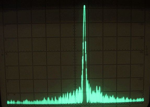
When you speak into your mic, the frequency of your voice is added to and subtracted from the frequency of the carrier, generating a group (or band) of sum and difference frequencies, called the upper and lower sidebands. We call them sidebands becuase they consist of more than one frequency, due to the fact that the human voice contains a number of harmonic frequencies (multiples of a fundemental, or base, frequency).

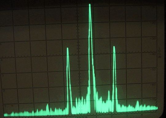
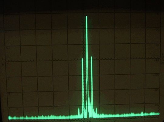
Below is a photo of the same signal above, but this time modulated by a signal of 3khz. You can plainly see the two sidebands to the left and right of the main carrier signal. The second picture below is the same signal, shown at a different resolution, so you can get a better idea of how narrow a proeprly modulated signal actually is. The total width of the signal shown is about 6khz, which is the width of the average CB channel (this width is determined by the receiver circuitry of the CB, and is designed to be only about 6khz wide to cut down on interference from adjacent channels).

mod1.jpg


mod2.jpg


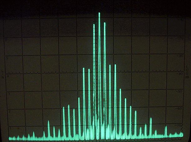
The following photo is of the same signal, now overmodulated. You can see how much wider the signal has become, with interference being caused over many channels above and below channel 21. The cause of overmodulation is generally clipped limiters and other improper tune-up and power modifications. In the case of this particular radio, the limiter was purposely overdriven to show what happens.

overmod.jpg


Quite some time ago, there was a thread about who was best to tune a Galaxy radio. In that thread, I posted some more info on this topic. Click Here to visit that old thread. The post I'm referring to is about a third of the way down the page.
 

Three things....

(1) were these above pictures taken using that homebrew spectrum analyzer circuit that you offer for sale for $25?

(2) Let's see what a "Clean" cb linear output looks like on your homebrew spectrum analyzer versus what a "Dirty" cb linear output looks like....

(3) Let's see an AMPOWER amp versus,say a JOKER amp for instance on your homebrew spectrum analyzer ........I think others here on the WWRF forum would be interested in seeing this also.....
 
We Three Things:

1. Nope, these were done on an HP mainframe unit with display storage ability (HP 141T display, 8554B RF unit, 8552B IF unit). The kit I sell is capable of about 6khz rez, but at the speeds it needs to scan in order to have a decently viewable trace, its not really narrow enough to get picky with individual channel cleanliness Its good enough to see bleedover on other channels, though.

2. Because the homebrew uses the CB as its RF/IF unit, it can only see the 11-meter spectrum area, which means you can't see the RF harmonics from an amp, other than the extra interference it may be causing on the 11-meter band.

3. See #2.

The kit I sell for $25 could be made to scan slowly enough to get fairly decent detail, IF you use it with a storage scope of some kind. The scope would have to have a persistant trace in order to see the data after the scan is complete. The scan speed would need to be in the ball park of one second, give or take, to get a really sharp trace.

As for amp comparisons, I'd be happy to do that. Have the makers involved each send me a straight 4-pill, and I'll put them through their paces. As my fee, I'll keep the one that I liked the best, and return the rest. I'll also promote the one I liked, post links to that makers webpage, etc.
 
Good post.What was the vertical scale in those pictures especially the last one with lots of "grass" in it? :) A good spectrum analyzer can be a techs best friend but an amp sellers worst enemy. ;)
 
I didn't use a specific scale. The tap was about a 50-50 tap, frequency-dependent, so all I was really after was the relative display. Due to the input of the analyzer being limited to a certain voltage, I need to buy (or put together) some precision attenuators before I'll be able to take specific numeric readings, other than relative DB differences.

One thing I didn't mention was that signals over about 30-50 % modulation showed additional sidebands at roughly 6khz, 9khz, 12khz, etc away from the center (carrier) frequency. If you look closely at the first photo of the modulated signal, you can just see the beginnings of the second sideband spikes to the right and left of the main sideband signals. The extra sideband signals were unexpected, and I'm assuming that they're due to additional non-linear mixing of the two main sidebands.

In retrospect, I probably should have expected to see them. I've noticed many times in the past that even a perfectly modulated signal tended to show some bleedover on closely-adjacent channels, but I had attributed it to the receiving radio just being close enough to experience front-end overload. Now I see that it was due to the extra sideband content.

This discovery also explained to me why alot of higher-end AM transmitter gear modulates the signal in an IF stage, then runs it through a narrow (6khz more or less) IF filter before mixing it up (or down) to the desired transmit frequency, and then sending it on to the power amp sections. This (for practical purposes) eliminates all of the extra sideband signals, leaving a nice, clean, 6khz signal with plenty of fidelity for voice transmission.

I want to add one more thought. The photos demonstrate the fact that, contrary to what some shops tell their customers, the carrier does NOT change in level during the modulation process, even in the extremely overmodulated photo. If you look closely, you can see that the carrier level stays the same in all of the photos (a bit over 7 divisions in each photo, with a slight variation due to me accidentally bumping the attenuator fine-tune on the analyzer). It is the sidebands, NOT the carrier, which contain the information. (Yeah, I know, most of us already knew that, but I've seen posts on here that say the carrier is shifted in power level. Heck, even I've been guilty of briefly explaining the AM process in that same way to very UN-techy people, just to save time.) The reason the carrier needs to be there (and in sufficient level, you idiots who like to cut the carrier down to almost nothing) is because the demodulation (the point in the receiver where the audio is extracted from the received signal) is basically modulation in reverse. You are un-doing the math of modulation, or to put it another way, you are un-adding and un-subtracting the modulation signal from the carrier. If the carrier isn't there, then you have nothing to un-add and un-subtract from, leaving a totally garbled signal, which sounds (surprise, surprise) like someone on sideband.

Was that a light that just went on in your mind??
 
That's a good thread on Quackshack. A nice piece of equipment, too. The only problem I have with that thread is at the end where they say it's not possible to get 40 watts or so out of a 1969 final without a ton of harmonics. While that's not gonna happen with any am/ssb/export models today, a pretty clean 40-50 watts without is certainly achievable out of some of the AM only radios.
 
  • Like
Reactions: freecell
my dimes worth

the 'extra' sidebands present in your test are normal. that is harmonic distortion products. you will see them at fc +/- 2fm, 2fc +/- 3fm, and so on. fc is carrier frequency and fm is the modulated frequency. you can measure these differences related to the primary sideband and get the amount of distortion as a percent. you can use the equation;

harmonic distortion = inv. log db/20

db is the difference between primary sideband and 2nd harmonic sideband. the db must use the - sign for the math to work out correctly.

example; a am signal is where the 2nd harmonic sideband is 28db below the primary sideband.

harmonic distortion = inv. log -28/20
harmonic distortion = inv. log -1.4
harmonc distortion = 0.0398
now multiply by 100 to change to a percent.
harmonic distortion = 3.98%

let me give the equation for finding modulation percentage when using a spec-an;

modulation = inv. log db/20 * 2
db here is sideband power below carrier
-------------------------------------

the actual reason the high dollar radios use low level modulation is because of $$$$. it is cheaper to use the same circuitry for ssb and am than to add the extra components for high level am. that is also why the newer hf rigs do not have the 'punch' of the older rigs that used high level modulation for am. plus, the manufactures know that the 'true' am'ers are fading away fast. so why waste the extra $$$$ to please them.
------------------------------------------

the level of the carrier -WILL- change if there is negative modulation, aka negative carrier shift or positive modulation, aka positive carrier shift. as an example if you have a radio that is capable of 20w pep and you raise the carrier to 10w, then you will see the carrier drop when modulation is applied. the carrier will actually drop to around the 5w level mark.
trust me i have 3 service monitors, hp8920a, ifr1600s, and a general dynamics 2600c. 2 of these have spec-ans with markers that can see down to the carrier and individual sidebands. i have tested this extensively.

just stating the facts.
 
are you sure?

sidebands are -6dBc when 100%

modulation = inv. log db/20 * 2

100% = inv. log 6/20 * 2?
 

dxChat
Help Users
  • No one is chatting at the moment.