
You are using an out of date browser. It may not display this or other websites correctly.
You should upgrade or use an alternative browser.
You should upgrade or use an alternative browser.
-
You can now help support WorldwideDX when you shop on Amazon at no additional cost to you! Simply follow this Shop on Amazon link first and a portion of any purchase is sent to WorldwideDX to help with site costs.
-
A Winner has been chosen for the 2026 July 4th Retevis RA89R Giveaway! Click Here to see who won!
Another PC122XL TX Problem
- Thread starter Low_Boy
- Start date
Andy I think you found something. Now I have to look at some schematics and find it on the radio. The 8V regulator is putting out 7.9V I will call that good. 8V supply rail is putting out the same 7.9V Good. VR3 has no power and JV28 no power. After I eat I will do some more looking.You asked a question earlier - check you TP mirror board jumper to ground - should have volts ALL THE TIME - yes that means it's got power and you can set AM power (carrier) while it's idle in AM mode. I just check it to make sure the AM regulator and Carrier power AM power - can adjust.
Else - note the length of jumper - when D38 is not working - you may have a blown trace from the rear of the board to the front - it's a PITA but get a magnifying glass and trace the routes and use a DVM to check for continuity.
I've had 122, 465 and 640e's blow traces - so it's nothing new...
The transistors need 8 volts from the main regulator to work, so if those traces popped, there's the reason.
Refer back to the graphic of the three transistors - look for 8 volts along that outer edge trace - that comes straight from the 8 volt regulator. So if the PLL works - you should have power along there.
The flat ribbon cable supplies power to the front panel - so if it doesn't TX - it means power is not "returning" to the front panel to turn on the TX lite - so that may mean the TX transistor may work, it's not sending power.
Ok, locate the ribbon cable that goes to the channel selector - with the radios component side up, the channel selectors - RIGHTMOST conductor in that ribbon, is your 8 volts to TX LED. - now what is different here, is you silence the speaker when you TX - so that tells me that TR33 should work but needed to be checked to verify - ok done, but it's not getting from the transistor to the left side, by the PLL and the Channel selector. - again check traces .... VR3 is the TX freq adj, - so I'm thinking a foil trace failure by VR 3.
So foil side up - locate the outer trace by those three TR33, TR32 and TR31 - and VR 3 - see if power get past VR 3 and towards the first pin of that ribbon connector - this time - it's the first one on the LEFT (Starting from the left)
:+> Andy <+:
BREAKING NEWS - Added this in...
View attachment 24418
:+> Andy <+:
Thank You.
I think I am getting lost, or too tired for today. L9 has no power. The cathode of D25 has power. the anode does not?
VR 3 ad J28 will only have power when CB./PA is in CB mode, you're TXing (INTO A DUMMY LOAD! CAREFUL!) in ANY AM SSB mode
Wonder if you have a bad trace on the front panel board that killed your TX and Pin 2 - these two are the upper two pins of the mike socket - No audio (Pin 2) and No TX (Pin 3)
Does Audio go quiet when you key the mike? (I think you said it did - but making sure...)
Because - D25 is the TX power diode for the SSB (not thru clarifier) D24 is the RX SSB clarifier - goes thru front panel....
So when you TX - D25 goes ACTIVE - POWER ON BOTH SIDES.
When in RX, you will have power on D25's THE BANDED end - but not on the other (Polarity - why it's a steering diode)
In RX D24 is what D25 was..
So, when in RX - D24 SHOWS POWER ON BOTH SIDES IN RX Mode ...
When you TX - D24 shows power only on BANDED Side.
We'll keep it simple for now...see if the above can help us sort it out...
:+> Andy <+:
I am working now not at the radio but. When the mic. Is keyed nothing changed. It does not kill the sound or key the radio. It does not seem to be switching.it is always in RX. With PA in or CB mode. No sound out of pa speaker when I talk in to the mic. And when Mic is keyed in pa mode sound is not muted. Thanks Andy.
Last edited:
You got it working?
Was the problem with the mic or blown trace...
Here's more...

The Mic Black and White wires are for AUDIO
The TX part, routes thru the CB/PA switch area - look at the photo the middle set of common contacts send the TX GROUND thru the ribbon cable down to the radios main PCB by the TR31 thru TR32 mess...
Was the problem with the mic or blown trace...
Here's more...
The Mic Black and White wires are for AUDIO
The TX part, routes thru the CB/PA switch area - look at the photo the middle set of common contacts send the TX GROUND thru the ribbon cable down to the radios main PCB by the TR31 thru TR32 mess...
It is not working. I am at work. Just a note though x2 is good but while in the radio showing no frequency .

May have to take the bezel off Uhhh. And peek inside. I am looking at the corrosive glue. I will do more probing first.
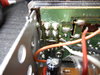
The "blistering" just above the spots you solder the audio and Mic Pin 1 (Shield/Ground/Common) where the White (audio to Mic amp) and Black (foil ground) in my photos are from the "glue" so it is possible that it can "peel" off the foil - a simple fix is to locate Pin 3 follow it to the ferrite beads (L553) top soldering spot and solder a jumper to that switch's middle pin closest to the mic jack - refer to photo for location - provided if the glue hasn't shredded the traces to the bead from the Mic Pin 3 jack.
If that restores TX - sorry about all the Transistor stuff - for Kaos was correct to check the CB PA switch, for the pole closest to the mic jack, is your CB/PA TX switch - for it then simply "grounds" No switching - TR30 "ON" and audio then shows up thru the Volume control - the other column of pins in the photo simply route the speaker out to the EXT Speaker jack in the back of the radio. There is nothing to force the TX mode - so essentially the radio is on, but the Transmit side is never turned on.
So with D38 never "on" let alone "off" - told me the TX side is still goofy and something is not making the Diode "Mute" the audio amp.
Somehow I thought I checked the pacb switch and I thought it showed voltage. I've had checked so much stuff I could be wrong.
You wouldn't necessarily see a voltage, it's when you keyed, the voltage would drop to zero at that part of the CB/PA switch (if you could get to it to check). IF Pin 3 works and TR33 turns on per TR32 Then D38 would show a voltage on both sides of the diode - because it's powering the "Mute" function of the Audio Amp Chip - that indicates the TX transistor was working - No TX lite would mean more of a blown trace to one side, - which you reference a bad PLL because the trace that goes to the TX lite - powers the Varactor and tells the PLL "I'm TX'ing"- so in light of all that has been said - each possibility needs to be checked - no matter how frivolous it may seem at the time because they are all potential routes and if checks aren't done - the radio still doesn't work...
In PA - the RX get's "SQUELCHED" when you ground Pin 3 when you key the mic . Diode D44 upsets the apple cart of IC1 M5223 - 1/2 of it anyways. - it conducts to ground and kills, Squelches, receive - so then the Volume control is free to take in what comes out of TR30 - the Mic amp that goes to the AM regulator, it sees the audio - and tries to send it - but it never transmits - no signal to turn on the bases of the TX line (TX power).
In PA - the RX get's "SQUELCHED" when you ground Pin 3 when you key the mic . Diode D44 upsets the apple cart of IC1 M5223 - 1/2 of it anyways. - it conducts to ground and kills, Squelches, receive - so then the Volume control is free to take in what comes out of TR30 - the Mic amp that goes to the AM regulator, it sees the audio - and tries to send it - but it never transmits - no signal to turn on the bases of the TX line (TX power).
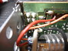
Andy with your help I spotted the problem. I have not fixed it yet but found it. Ground/common on mic. plug makes no continuity with any thing on the board. Pin 4 may be a problem also. The mic. socket must have taken a hit Picture inclosed. I did peel this a bit more than it was. May not get back to this until Sun.
Attachments
Good catch!
Pin 4 and Pin 1 short together.
The ring shorts to - nothing - RF bypassed to ground thru a cap so Jacks own metal frame is DC isolated - no shorts.
The Pin 1 and Pin 4 - SHORT TO THE BLACK WIRE in photo - that is foil ground - at the radio.
I see something may have struck the jack - tearing up some of the foil traces and may be...even breaking some of the pins at the jack itself - you'll need to probe to make sure that the pin is still electrically connected to the solder pad it is supposed to be.
dxChat
- No one is chatting at the moment.