• You can now help support WorldwideDX when you shop on Amazon at no additional cost to you! Simply follow this Shop on Amazon link first and a portion of any purchase is sent to WorldwideDX to help with site costs.

Antenna Experts Needed: Common mode filter issue

NightOwl3261

Well-Known Member
Jul 24, 2020
140
202
53
65
Included photos of filter in question and specifications of said filter. Here is the issue. The issue appears on 2 different antennas, but I will use the Sirio Gainmaster antenna for the example of the issue. Keep in mind I tested the common mode filter into a dummy load and the SWR is 1:1 so not a defective choke. The issue is as follows.
SWR is a flat 1:1 on the gainmaster from 26-28 Mhz. Added choke right at entrance of coax into shack and SWR increases to about 1.5:1-1.7:1 from high end of 11 meters and increases as it goes into 10 meters. Go to low end of 11 meters and SWR drops into the 1.1:1-1.2:1 range. At the very top of 10 meters goes to 2.0:1. Another issue to add to the mix is that changing jumper lengths between the choke and the SWR meter changes SWR better or worse depending on length of jumper. The Gainmaster has a built in choke as you know, but as a force of habit I installed an additional ferrite choke at base of antenna. Without a choke at entrance to shack, SWR is flat as a pancake with the broadbanded gainmaster.
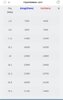
I included the specifications of the choke at each frequency In case that may be involved in what is taking place. Sure I could drop the SWR with the antenna tuner, but that seems counter productive as a bandaid, but I could be wrong about that. Please give me y'all's expert opinions of what is taking place. I also have a Sirio 2016, and it shows similar behavior to the above. But the gainmaster is a better example in regards to specifically what is taking place. Why the heck is this 1:1 common mode filter effecting SWR when installed at the shack end of the antenna system? Why does it get worse as operating frequency gets higher? Should I tune it out with the antenna tuner or is that just covering up the issue? Why does the jumper length between the choke and the SWR meter change the SWR? With the gainmaster's built in choke and an additional choke at the feed point, I feel I can't have a huge common mode problem with that particular antenna. The choke at the shack end was meant to be no more than precautionary and an experiment to see if it would effect noise at the receiver. HELP!
 

Attachments

  • Screenshot_20211221-225341_Samsung Internet.jpg
    Screenshot_20211221-225341_Samsung Internet.jpg
    109 KB · Views: 194
  • Screenshot_20211221-225330_Samsung Internet.jpg
    Screenshot_20211221-225330_Samsung Internet.jpg
    95.1 KB · Views: 181
Last edited:

Is having baluns installed at different distances, like actually using two antennas connected in series? (My brain is going to hurt before this is over.)
 
  • Haha
Reactions: groundwire
I by habit install chokes at the feed points of antennas including the Gainmaster to reduce common mode on the feedline. Being that the Gainmaster already has a built in choke as part of the design, it would seem that an added choke at the feed point would either be doing nothing if the Gainmaster choke works as designed, and the added choke may enhance the gainmaster's choke further. As far as at the shack end, I have had luck through the years in a reduction of noise at the receiver as have many people. Any electrical noise picked up by the shield sometimes improves with a choke at the shack end.
 
A couple of things come to my mind. From my experience and if I understand it correctly, if you antenna has a good RF ground to work against, then you will see very little if any, common mode currents on your coax during transmit. If you are seeing RF on the shield of your coax, either the antenna has insufficient RF ground and using your coax shield and anything else its connected to (not good) for RF ground, or the antenna is designed to use the coax braid as an RF ground as in a NGP antenna. In my honest opinion having built all of my own antennas, the first thing you need to work out is your RF ground, whether it is radials, counterpoise wires, a ground rod, metal roof, gutters, etc.. Also if you measure a 1:1 SWR at the antenna, and the antenna is working right, you will also measure a 1:1 with an analyzer with the coax hooked up. Remember, ANY time moving, touching, changing length of coax, etc. changes your SWR, your coax is part of the antenna. Solve this first and your antenna will get more signal in the air for you.

I just though of something else, are you running a tuner?
 
  • Like
Reactions: groundwire
Are you running a lightning protector to ground at building entry? I put my common mode filter box (small one) at my lighting protector which is screwed to a ground rod. Band scope looked like a roller coaster before I installed the filter on my WFHW. SWR stayed same across my bands.
 
I think what you have done by adding an additional balun/choke has made the gainmasters built in choke less effective, therefor allowing for CMC's to be present on your coax shield.

The number of turns on the GM choke has been "tuned" for best performance on 27MHz and you have effectively wound more turns on and detuned it by adding more series L to the shield with the extra balun/choke. More turns is not always "better".

If changing jumper length changes SWR readings then you have CMC's present.

I would remove the feedpoint choke you have added then try again. I have a homemade 1:1 balun at my radio and makes no difference if I plug my homemade gainmaster inline with the balun or direct to the radio.
 
Last edited:
  • Like
Reactions: magnuman
I think what you have done by adding an additional balun/choke has made the gainmasters built in choke less effective, therefor allowing for CMC's to be present on your coax shield.

The number of turns on the GM choke has been "tuned" for best performance on 27MHz and you have effectively wound more turns on and detuned it by adding more series L to the shield with the extra balun/choke. More turns is not always "better".

If changing jumper length changes SWR readings then you have CMC's present.

I would remove the feedpoint choke you have added then try again. I have a homemade 1:1 balun at my radio and makes no difference if I plug my homemade gainmaster inline with the balun or direct to the radio.
Agreed. Take off the added choke you put at the base of the gainmaster and see what changes if any the shack choke makes. All end feds seem to work better with some unchoked coax under them.
 
The 1:1 RF choke should be placed as close as possible (within 1'-8') of the antenna coax feed point.
You want to keep all the RF up at the antenna and none coming back down the shield of the coax.
All my antennas are set up this way. Vertical, horizontal yagi, OCF dipole antenna.
I have no RF feedback coming back down into my radio room, and very good VSWR regardless of coax length or jumpers length.
 
  • Like
Reactions: Hurricane145
I had a commercially made Common mode choke some years ago. I first placed it just outside the shack and there was little difference. Then I added a long piece of coax and set the choke way out in the yard and it did make some difference but the added coax may have done that, not sure. I eventually added one I made up at the feed point of my 5 band quad and that solved all the RF in the shack problems.

It really makes sense to have it at the feed point. It's the furthest point from the rig/shack so any radiation from it is also furthest away. If it is very near the shack, the radiation from the coax up to the choke may still be pretty strong in the shack and can disturb some equipment.

I wouldn't expect a common mode choke to kill any receiver noise, just reduce any RF getting into the shack and getting into the rig or computers etc.

A good line filter may do well in reducing receiver noise.
 
This is from K1TTT technical reference. It is what I used for making a coax choke. The larger article elaborates on this and is much more technical but these were his findings in conclusion.
It can be a bugger to wind RG-213 on a 4 inch piece of PVC but it can be done with good plastic cable ties.

Conclusions
-----------
- A 1:1 coaxial balun with excellent choking reactance for 10 through
20 meters can be made by winding 6 turns of RG-213 on inexpensive 4
inch PVC sewer pipe.


- For 40 or 30 meters, use 12 turns of RG-213 on 4 inch PVC sewer
pipe.

- Don't bunch the turns together. Wind them as a single layer on a
form. Bunching the turns kills the choking effect at higher
frequencies.

- Don't use too many turns. For example, the HyGain manuals for my 10
and 15 meter yagis both recommend 12 turns 6 inches in diameter. At
the very least this is about 3 times as much coax as is needed, and
these dimensions actually give less than the desired choking impedance
on 10 and 15 meters.
 
I've just read through this again wondering if the OP had ever replied, and I thought of a better way of explaining this...

If you look at a trapped dipole for say 10/15/20 meters. the traps are just an LC band stop filter that is tuned for a specific frequency. So the first trap on said dipole would be tuned for maximum impedance at 10 meters, this to RF looks like the end of the antenna, and no RF travels past the trap (in a perfect world). As you move away from 10 meters in frequency the trap becomes less effective and when you get down to 15 meters the trap will (again in a perfect world) be almost invisible to RF and just become a loading coil in the radiating element.

So the Sirio design uses the outside of the braid of the coax inside the tube as the lower half of the dipole, and the red coax coil may be better thought of as an LC filter, or trap, that is determining the end of the element.

Adding more coax turns, inductance or capacitance at the so-239 feedpoint of the antenna (which is not really the feedpoint, the coax continues inside the antenna to the middle) is just the same as retuning the trap for another band, making it less effective on CB.

You can see on the air cored part of the chart sp5it posted, more turns of coax shift the maximum impedance point lower in frequency, which is what has happened to the OP.
 

dxChat
Help Users
  • No one is chatting at the moment.
  • dxBot:
    Tucker442 has left the room.
  • @ BJ radionut:
    LIVE 10:00 AM EST :cool:
  • @ Charles Edwards:
    I'm looking for factory settings 1 through 59 for a AT 5555 n2 or AT500 M2 I only wrote down half the values feel like a idiot I need help will be appreciated