I see some similar Patterns between the Pattern View in the article and my Eznec, but this software program likely uses a lot more "smoothing" and details in their images.What do you believe the image or the text ?
Let me read the text again,

I see some similar Patterns between the Pattern View in the article and my Eznec, but this software program likely uses a lot more "smoothing" and details in their images.What do you believe the image or the text ?

Again, I will comment when I get my Eznec back and am able to model that conventional 1/4 wave GP.Yes I just noted the models imagery seem to tell a different story than the words in that particular article.
Again, I will comment when I get my Eznec back and am able to model that conventional 1/4 wave GP.
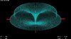
The text is in complete agreement with the polar elevation image presented. It is clear that the larger portion of the radiated power is present in the upper high angle lobe.
However, it would seem to me that what could "bring you up into DXCC highscore" would be increased levels of power in the lower of the two pattern lobes instead of wasting power at the higher angles, unless of course you're into multi-hop propagation.
")
")
Hi, TB.Can you please explain how does the "hat rim" going beyond that of the top of the hat represent "the larger portion of the radiated power is present in the upper high angle lobe." (on what must be the X axis in dB)
Peak gain looks very obviously to be at a lower angle. See the red below on attached image that is a lower angle not higher. This is my last post on this because it is so unbelievably obvious that I cannot waste further time of my life on it. if you cannot see it then so be it.
Thanks Marconi GPA looks like it should DX just fine at 0.25 wavelength, at least in the model.