I am trying to build a 3 element PDL can you please post the measurements for the wire, linth of the arms and the spacing of the director element?The only non conductive hub is the one on the driven element. The directors are set up like the reflector.
I have the measurements for a three element but not a four!

You are using an out of date browser. It may not display this or other websites correctly.
You should upgrade or use an alternative browser.
You should upgrade or use an alternative browser.
-
You can now help support WorldwideDX when you shop on Amazon at no additional cost to you! Simply follow this Shop on Amazon link first and a portion of any purchase is sent to WorldwideDX to help with site costs.
-
A Winner has been chosen for the 2026 July 4th Retevis RA89R Giveaway! Click Here to see who won!
antenna project pdl-II made into a quagi please help antenna qurus!
- Thread starter sob
- Start date
Top secret! ShhhhI am trying to build a 3 element PDL can you please post the measurements for the wire, linth of the arms and the spacing of the director element?
Attachments

Archer Crossbow sold by Radio Shack back in the early 80's
Cat. No. 21-967.This is made of light blue fiberglass
Back to topic
Cat. No. 21-967.This is made of light blue fiberglass
Back to topic

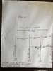
Appaloosaguy, the regular two element PDL shows to have a driven element wire that is 458" inches total length. That is 9'6" inches per 1/4 wave side or 114" inches. For CB this one is a lot longer than 108" or less inches if used in the middle of 11 meters and using thin wire makes it worse. If you are going for 10 meters you'll need to get out your trusty slide rule.
I don't know for sure what the reflector length is by reading the Manual, but my copy has a hand written note of the cover page with an arrow pointing to the reflector wire along with a note showing 462.5" inches. That is not much difference but this antenna is inductive and along with the orbital matching setup using a gamma match the 458" inches for the driven element may electrically appear much shorter and that will make the reflector bigger as a %.
The spacing shows 55.125" inches between the center of the hubs. To be clear the spacing is in the manual.
As a starter I would make the director hub easily adjustable and start with 55" inches just like R to Dr. If you're lucky and are able to get close to a match with your 3 elements...you might do a couple of short spacing adjustments with the director, making it longer and shorter spacing, and see how it effects the match. You will have to be close with the gammas first however, to really tell.
It might be best to get the two element working first and then install the 3rd element so you might avoid chasing your tail just trying to get close.
Tuning this one could be a beast having to tune gammas and not being sure about wire lengths and spacing to boot, much less adding another element where everything could change.
I read an account of one guy building this idea from scratch, and he spent a long time getting it working right.
Just remember this antenna, with gamma matching is going to be longer than you might expect and for sure if your using standard formulas.
Good luck and keep us posted,
View attachment 21222 I know this is a long shot but I wonder if anyone knows what this antenna is. I bought it from an older guy who said it was a Realistic from the 1970s. It has 2 sections, 6 feet each, that screw together.
I have the 1/2 wave Archer (Radio Shack) Crossbow. It is simply a Shakespeare Big Stick dyed in blue for Radio Shack to sell. Purchased in the early 80s, mine is still in service. SWR readings are essentially flat across the 40 channel CB. I just checked them again last night.
The two sections should be 9' each - not 6. The top section whip has a reverse thread onto the bottom section.
Hope that helps.
sob, you could try tuning the driven elements for the pdl2 first without reflector/directors. When you got that close, then start adding the other quad elements, one at a time, and retuning as necessary.
I had a local buddy in the 80's that made a four element quad (not a quagi) using a PDL2 driven element setup and it worked very well. He tried to build it all at once by himself. He took over a year at the effort, but it would not work until he paid a local communications engineer with the Harris County Sheriff's office to set it up right. As far as I know the driven emement was not modified in any way different than the PDL2. This engineer rebuilt the beam just like I described above, get the driven element to tune, and then add the reflector first to tune, and then add the two directors, one at a time, tuning as he went.
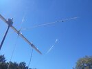
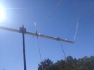
ok i am kinda the believer that thinks after 5 to 6 quad elem. it gives no further gain ro add elements. so i want to build a "quagi" for 11m. i have the 2 elements (reflector and driver ) made. used SE lightening as a pattern for my feed. copied it from our L6. the spacing of these 2 are 84 inches apart. only reason for that is the L4 spacing starts that way. these can be adjusted if needed. i know the layout on L6 is not the same. the question is how would one space the YAGI elements down the boom?. do i treat this as a quad and space them the same or treat it as a yagi and stretch them out as i go down the boom? boom is 3 in so maybe 9-10 total elements. we are after more forward gain. not wide pattern or band width.
we now run a 7 elem direct feed horz. yagi. followed the footprint of a maco. only thing we did different was space the last couple directors out to gather more forward gain.
in the pics the mount for the mass is a temp just to work off of. not the final resting place obviously.
we are open to any suggestions
Attachments
Last edited:
View attachment 7390
This is a PDL4, 14 "TRUE" db gain. A guy here in Oklahoma has spent the last many years perfecting it! He also builds a PDL3 as well. Horizontal and vertical work very well. They are real tight and have great rejection!
By the way if someone does talk you into selling anything PDL and you don't have a crazy price on it. Get ahold of me! I'm putting together parts for a PDL3!
Thanks and good luck!!
Can you share the measurements for a pdl3The only non conductive hub is the one on the driven element. The directors are set up like the reflector.
I have the measurements for a three element but not a four!
The only non conductive hub is the one on the driven element. The directors are set up like the reflector.
I have the measurements for a three element but not a four!
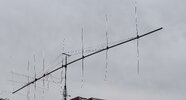
this is actually a quagi 50ft boom mono band 11m. sfs feed all elements are insolated. back end reflecto and driver are quad loops and the rest are yagi type element. this is what we did today. reconfigured the element layout. but only got the verticals done. we will add one more section of boom on the front to add the 9th element the horz elements in a couple days...
Attachments
Bump
During the day when I have a few minutes, I often day dream about putting up a big antenna.
During the day when I have a few minutes, I often day dream about putting up a big antenna.
I have build quads to 11m band and few notes.
First 2el.
1.3m boom and 2mm copper wire works great.
Impedance match 1/4 wave 75ohm coax.
BW ab. 1 MHz swr 1:1.5.
3el not work because mast tube is too close to feed point.
It just kill the antenna.
4el works fine 6.5m boom, 50ohm feed with balun.
BW 500k
5el works great, 9.6m boom.
BW 800k
6el superb. 13m boom .
BW 500k
Gain is ab. 1db more then 5el quad.
dxChat
- No one is chatting at the moment.