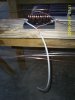
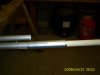
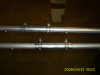
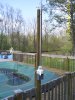
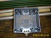
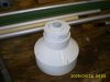
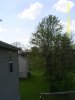
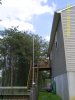
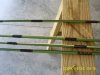
Well after a couple of weeks experimenting with an end fed wire antenna for 11 meters and trying to get the matching cicuit right (and fighting with my OCD :blink") I have started the "final" design of my vertical ground plane antenna. Once I got the matching circuit right (photo 1), I ended going with an air wound coil and a coax capacitor which brought the SWR down to 1.5:1 on the wire antenna and I'm pretty confident I can get this setup to work with the vertical. I was able to pickup some aluminum tubing that is 7/8" in diameter and about 5' long. I joined them with a two foot wooden dowel and a coupler made from conduit and hose clamps (photos 2 & 3). The overall length is 22.5 feet and seems to be very strong and lightweight. Photo 4 is the completed radiator attached to the base and the enclosure for the matching cicuit. Photo 4 also shows the mount and support which is pressure treated 2x4's I had laying around which is designed to transfer the wind stress around the base and enclosure straight to the antenna mast which will be 1.25" conduit extending all the way to the ground from the roof peak. Photo 4 shows the antenna attached to my pool deck and is currently going through wind testing. So far so good, had a good windy one on Saturday and the only thing I had to change was the length of the radiator support, the weight of the antenna was pulling it over from upright.
I have started the "final" design of my vertical ground plane antenna. Once I got the matching circuit right (photo 1), I ended going with an air wound coil and a coax capacitor which brought the SWR down to 1.5:1 on the wire antenna and I'm pretty confident I can get this setup to work with the vertical. I was able to pickup some aluminum tubing that is 7/8" in diameter and about 5' long. I joined them with a two foot wooden dowel and a coupler made from conduit and hose clamps (photos 2 & 3). The overall length is 22.5 feet and seems to be very strong and lightweight. Photo 4 is the completed radiator attached to the base and the enclosure for the matching cicuit. Photo 4 also shows the mount and support which is pressure treated 2x4's I had laying around which is designed to transfer the wind stress around the base and enclosure straight to the antenna mast which will be 1.25" conduit extending all the way to the ground from the roof peak. Photo 4 shows the antenna attached to my pool deck and is currently going through wind testing. So far so good, had a good windy one on Saturday and the only thing I had to change was the length of the radiator support, the weight of the antenna was pulling it over from upright.
More to come. Any suggestions welcome.
John
I have started the "final" design of my vertical ground plane antenna. Once I got the matching circuit right (photo 1), I ended going with an air wound coil and a coax capacitor which brought the SWR down to 1.5:1 on the wire antenna and I'm pretty confident I can get this setup to work with the vertical. I was able to pickup some aluminum tubing that is 7/8" in diameter and about 5' long. I joined them with a two foot wooden dowel and a coupler made from conduit and hose clamps (photos 2 & 3). The overall length is 22.5 feet and seems to be very strong and lightweight. Photo 4 is the completed radiator attached to the base and the enclosure for the matching cicuit. Photo 4 also shows the mount and support which is pressure treated 2x4's I had laying around which is designed to transfer the wind stress around the base and enclosure straight to the antenna mast which will be 1.25" conduit extending all the way to the ground from the roof peak. Photo 4 shows the antenna attached to my pool deck and is currently going through wind testing. So far so good, had a good windy one on Saturday and the only thing I had to change was the length of the radiator support, the weight of the antenna was pulling it over from upright.More to come. Any suggestions welcome.
John