• You can now help support WorldwideDX when you shop on Amazon at no additional cost to you! Simply follow this Shop on Amazon link first and a portion of any purchase is sent to WorldwideDX to help with site costs.

Astatic 575M-6 mic wiring question?

long night

Active Member
Jan 8, 2020
202
39
38
75
Hito all. Can someone tell me which wire color on an Asytatic575M-6 is the hot wire. Is it white or another color?
Thanks
Chuck Saylor
 

Hot wire?
What radio are you wanting to wire it to?
The mic is wired to my Cherokee 1000 base radio. The iisue is the wires to the battery broke off flush with the pcb board and I can not reattach them as they were before they broke off. I can attach the negative wire to the stranded wire where it has a solder connection as it enters the inside of the mic on the pcb board for the ground, but I need to know what wire is powered to solder the positive connection to. I think it is white but not sure?
 
Here is the manual
Hi Greg T. Thanks for the info, but it does not help. I am unable to reattach the battery wires as they were, so my plan is to attach the negative ground battery wire to the stranded ground wire were it attaches to the pcb board on the inside of the mic. If I can tell which wire is hot coming into the mic I can attach the battery positive wire to it where it enters the mic and attaches to the pcb board.
 
Hi Greg T. Thanks for the info, but it does not help. I am unable to reattach the battery wires as they were, so my plan is to attach the negative ground battery wire to the stranded ground wire were it attaches to the pcb board on the inside of the mic. If I can tell which wire is hot coming into the mic I can attach the battery positive wire to it where it enters the mic and attaches to the pcb board.
You need a DVM, do you have one?

You need a volt meter to see which wire has a +ve voltage on it coming from the radio.

It might not be the best idea though, what if the mic pulls more current than the radio can provide?

Might be best just to fix it so you can refit the battery...
 
Hito all. Can someone tell me which wire color on an Asytatic575M-6 is the hot wire. Is it white or another color?
Thanks
Chuck Saylor
It sounds like you want to power the mic without having a 9 volt battery installed. I have never seen this done on a 575. None of the mic cord wires ever have power or are "hot" on this mic.
 
Actually it is a bit tricky. You can pull the board out of that microphone. Be careful you cant buy replacement parts. On the top side of the board you will see B+ and B-. After you remove the board you can put in a new battery hook up and solder from the bottom. And it is harder getting this all back together.
 
Actually it is a bit tricky. You can pull the board out of that microphone. Be careful you cant buy replacement parts. On the top side of the board you will see B+ and B-. After you remove the board you can put in a new battery hook up and solder from the bottom. And it is harder getting this all back together.
I have had the board out of the mic before. I can see the back of the board, but it is hard to tell which solder spot is the negative one. Do you have a picture of that? Thanks
 
It sounds like you want to power the mic without having a 9 volt battery installed. I have never seen this done on a 575. None of the mic cord wires ever have power or are "hot" on this mic.
A picture of the back of the board showing which solder spot is the negative one would be quite helpful.
Thank you.
 
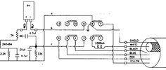
1650166737513.png

In this diagram you can see that the red wire attaches to one side of the 5K adjustment pot, and it is the only thing connected to that side of the pot.

the black wire gets attached to pin 9 of the mic switch. the switch may not be labeled so you can confirm you have the right pin by using your multimeter set to read continuity.
most meters these days will have a setting that will beep when you touch the meter probes together allowing you to find two points on a circuit board that are connected without having to look at the meter.

If you put one probe on the shield wire of the mic cord and the other on one of the solder lugs on the back of the switch, you can find out which pin is pin 8, which will be right next to pin 9.
you would also notice continuity if you put the probe on pin 7 since pin 7 and pin 8 are connected in receive.
if you were to put a rubberband on the mic button so it stays keyed, you would find that you have continuity from the shield wire to pins 8 and 9 because the idea is to only ground the negative terminal of the battery when you push the mic button.
they do it this way so that the battery doesn't go dead from just sitting there.

now that you know which pin on the switch is pin 9, you can put one of your probes on pin 9 and then touch it to one of the solder pads where the battery wire pulled out of.
if you get a beep from your meter, you know you've found the right pad for the negative side of the battery.

you can do the same for the positive side by putting one meter probe on the empty side of the 5K pot, and then the other probe on one of the solder pads where the battery wires pulled out. if you get a beep you've found where the positive wire will solder to.
LC
 

dxChat
Help Users
  • No one is chatting at the moment.
  • dxBot:
    Tucker442 has left the room.
  • @ BJ radionut:
    LIVE 10:00 AM EST :cool:
  • @ Charles Edwards:
    I'm looking for factory settings 1 through 59 for a AT 5555 n2 or AT500 M2 I only wrote down half the values feel like a idiot I need help will be appreciated