
Its the same PLL they use in many of these newer radios (like the PC68LTX, see this post), but since the data could be different, this one is getting its own thread. Its time to find out. Spoiler, although the data is similar to the PC68LTX, it is not the same.
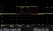
Green is chip select, yellow is data, and pink is clock (vertical scales offset a little to help separate the colors). The first thing that I see is that not all the data is for the PLL. Only some of it happens with the chip select on the PLL high so the micro is talking to more than just the PLL. But the two sections where chip select (green) is high, I see the familiar reference divider then loop divider data pattern as in the PC68.

This is what is seen keying the mic on ch1

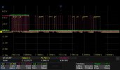
This is zoomed in on the first section with CS (green) high, its the TX reference divider data

If you want to decode this, the PC68 post linked above explains it, so I'll just provide the answer here. This translates to a HEX code of 1000, or a dec value of 4096. 10.24MHz/4096 = 2.5kHz at the phase detector. Like before, the last bit tells it that its for the reference.
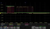
The second part with chip select high (the TX loop divider data)

Here, we have a hex code of 196C, or 6508 in DEC, and 2.5kHz*6508=16.27MHz. Going back into RX when unkeying, .....its the same data. This is where the 980 and PC68 synthesis part ways (besides the phase detector frequency and SSB stuff of course).
Rather than using the PLL to shift for TX/RX like the PC68, it is selecting between mixing with the 10.24MHz and 10.695MHz crystals
.
In TX you have 16.27MHz+10.695MHz=26.965MHz and in RX you have 16.27MHz+10.24MHz=26.51MHz (offset by 455kHz).

How convenient, you only need to give it one code for both TX and RX") That might make things easier to arduino!
That might make things easier to arduino!
Edit: So that makes me wonder what Les did. Did he change that code bank for all 40 channels or did he swap the 10.695 and have TX only in freebanded?
Thats it for tonight, headed to bed.
Green is chip select, yellow is data, and pink is clock (vertical scales offset a little to help separate the colors). The first thing that I see is that not all the data is for the PLL. Only some of it happens with the chip select on the PLL high so the micro is talking to more than just the PLL. But the two sections where chip select (green) is high, I see the familiar reference divider then loop divider data pattern as in the PC68.
This is what is seen keying the mic on ch1
This is zoomed in on the first section with CS (green) high, its the TX reference divider data
If you want to decode this, the PC68 post linked above explains it, so I'll just provide the answer here. This translates to a HEX code of 1000, or a dec value of 4096. 10.24MHz/4096 = 2.5kHz at the phase detector. Like before, the last bit tells it that its for the reference.
The second part with chip select high (the TX loop divider data)
Here, we have a hex code of 196C, or 6508 in DEC, and 2.5kHz*6508=16.27MHz. Going back into RX when unkeying, .....its the same data. This is where the 980 and PC68 synthesis part ways (besides the phase detector frequency and SSB stuff of course).
Rather than using the PLL to shift for TX/RX like the PC68, it is selecting between mixing with the 10.24MHz and 10.695MHz crystals
.
In TX you have 16.27MHz+10.695MHz=26.965MHz and in RX you have 16.27MHz+10.24MHz=26.51MHz (offset by 455kHz).
How convenient, you only need to give it one code for both TX and RX
That might make things easier to arduino! Edit: So that makes me wonder what Les did. Did he change that code bank for all 40 channels or did he swap the 10.695 and have TX only in freebanded?
Thats it for tonight, headed to bed.
Attachments
Last edited:


