
You are using an out of date browser. It may not display this or other websites correctly.
You should upgrade or use an alternative browser.
You should upgrade or use an alternative browser.
-
You can now help support WorldwideDX when you shop on Amazon at no additional cost to you! Simply follow this Shop on Amazon link first and a portion of any purchase is sent to WorldwideDX to help with site costs.
-
The Father's Day Retevis RA89R Winner is Announced! Click Here for more info!
Bias design, amplifier design, filtering etc.
- Thread starter -=PEAKABOO=-
- Start date

Hello Jeff: Ok thanks for the info here I printed out the bias sites for reading. I have a circuit I made a few years ago using a voltage regulator a Zener diode and another voltage regulator,... I think. It regulated right at the 1 volt level at 3 amps.
I was impressed with the guys 3 bias circuit in the past postings. Came across a 8 pill that needs bias for SSB, probably will use 4 bias circuits for that while watching a scope and spectrum analyzer. Another project great....
Jay in the Great Mojave Desert
I was impressed with the guys 3 bias circuit in the past postings. Came across a 8 pill that needs bias for SSB, probably will use 4 bias circuits for that while watching a scope and spectrum analyzer. Another project great....
Jay in the Great Mojave Desert

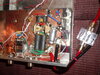

Is that the Joker amp from back in the day? I was trying to find my Joker amp recently, and it looks a lot like yours. The diamond plate and the heatsink sandwiched with the n on top. It's a base unit with 2290's and some nice filtering. I think I bought it off this site, of Moleculo -- had to be early 2000's. It's been sitting in a box on the shelf for years.....Is there a demand for these things?Sure wish PEAKABOO was still building. Wish I still had my Joker, it was two 2879's with regulated AB bias.
I had a joker once. Long skinny 6x I think it was diamond plate ... I saw it listed in some Dallas cb shop on FB a while back but they sold it again before I had a chance to inquire and see if it was my old one.Is that the Joker amp from back in the day? I was trying to find my Joker amp recently, and it looks a lot like yours. The diamond plate and the heatsink sandwiched with the n on top. It's a base unit with 2290's and some nice filtering. I think I bought it off this site, of Moleculo -- had to be early 2000's. It's been sitting in a box on the shelf for years.....Is there a demand for these things?
In reference to this message...
 www.worldwidedx.com
This thread brings up the subject of Biasing for the GrantXL and the Cobra 148 - especially around the Final Area...
Many have wondered about the use of TR37 in biasing the Final...

This article is a snippet of that PDF - shown below, to help clarify that process.

It provides a stable current to keep the 1969 forward biased - making it an effective method to keep SSB low-level volume signals from getting cutoff - and to allow peak SSB amplitude signals from getting clipped excessively as compared to when you use a SINGLE diode bias reference that can drop out due to the current draw thru the divider circuit causing a starvation contention.
Bias design, amplifier design, filtering etc.
where is the band switch? (jk) It was not requested:tongue:
This thread brings up the subject of Biasing for the GrantXL and the Cobra 148 - especially around the Final Area...
Many have wondered about the use of TR37 in biasing the Final...
This article is a snippet of that PDF - shown below, to help clarify that process.
It provides a stable current to keep the 1969 forward biased - making it an effective method to keep SSB low-level volume signals from getting cutoff - and to allow peak SSB amplitude signals from getting clipped excessively as compared to when you use a SINGLE diode bias reference that can drop out due to the current draw thru the divider circuit causing a starvation contention.
- - so you know many other SSB-radios use a divider circuit as a default.

I have often wondered about the choice of diode in the driver bias circuit like D46 below. I happen to look down at my variable power supply and saw a laser diode and I recalled a time when I would drive laser diodes until they gave up the smoke. Figured I would share how I made sense of this diode for others that might want a simple explanation.

Have you ever connected a LED to a variable supply without a current limiting resistor? With careful control of the voltage, you can avoid burning out the LED. In fact, you can quite accurately set the current through it if you carefully adjust the voltage to it. They don't just turn on all at once, they come on exponentially. That means small changes in voltage cause large changes in current and vice versa. So, lets say we connect the driver base directly to our variable power supply as if it were the LED and slowly raise the voltage until we get our desired collector current. Write that down and also write down the current from the variable supply biasing the base. A variable resistor between the 8v supply and the base (with no diode) will have way too much range and within a small amount of rotation, the transistor will go from off to fully on and you'll have a hard time stopping at 50mA. What if we found a diode that, at about 10x the base current, had a voltage drop matching what we needed at the base to achieve the desired collector current? Having the diode allows a large change in current to make a small change in voltage, and that allows for a fine adjustment of the bias current. The resistor values are chosen so that the range in current adjustment moves the diode forward voltage drop above and below the voltage we determined we needed for the 50mA or whatever collector current. Think adjustable voltage regulator with a very narrow range. Those laser diodes did not die in vain.
Edit: Temperature compensation just clicked for me while thinking about this. If you fed the transistor base a constant current and recorded its voltage drift with temperature, you could find a diode that, when biased to match the transistor, its Vf drifted the same amount as the transistor, then attaching that diode to the transistor would lower the bias voltage (thus current) as to maintain that constant current as it warms up. I know thinking about BJTs in terms of bias voltage with the emitter grounded is hard to understand, but remember, that 0.6v Vf isn't rock solid, its dependent on current. So thinking in terms of voltage works if your DMM has more than 2 digits.
Last edited:
Is Steven Tucker still around? I regret selling my Joker Box 20 years ago and want another one.
dxChat
- No one is chatting at the moment.
-
-
-
dxBot:boog351 has left the room.
-
@ BJ radionut:
June VHF
The American Radio Relay League (ARRL) is the national association for amateur radio, connecting hams around the U.S. with news, information and resources.www.arrl.org
-