
You are using an out of date browser. It may not display this or other websites correctly.
You should upgrade or use an alternative browser.
You should upgrade or use an alternative browser.
-
You can now help support WorldwideDX when you shop on Amazon at no additional cost to you! Simply follow this Shop on Amazon link first and a portion of any purchase is sent to WorldwideDX to help with site costs.
-
A Winner has been chosen for the 2026 July 4th Retevis RA89R Giveaway! Click Here to see who won!
bob85 schematic
- Thread starter nav2010
- Start date
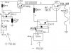

Actually there is a missing diode on this particular circuit. Plus resisters R2 and R4 have missing values. Any ideas fodendaf?are you going to put a feedback loop in it to raise the efficiency?
This particular choke is called a Hip Hip Op choke. :laugh:
Honestly it's hard to predict what value r2 and r4 have without knowing the part number of the pwm ICs.
PWM - Pulse Width Modulation for DC Motor Speed and LED Brightness - Robot Room this website points to a 10k pot for both r2 and r4 but says you need two diodes to vary the on and off times.
Since the IC on the right appears to be for varying the duty cycle and there is only one diode in the optoisolator I would wire another diode in opposite direction in parallel to the optoisolator diode. as per the circuit in that link. Hook the wiper to the pwm ic to replace the resistor in circuit and each other leg goes to each diode.
If you examine the circuit in that link you can see there are several 0.1uf 104 caps missing from your circuit also which it will not function without.
If you examine this link How to Make a Simple IC 555 PWM Circuit you can see that the pwm IC on the left is set up as an astable multivibrator and the ic on the right is a PWM so I would build those circuits first and then worry about integrating the design in to your circuit or download the datasheet for what you have and build both circuits from the examples listed.
The maximum current permissible on R2 and R4 is 60ma. This is the spec for the optocoupler diode on the input side. 1k is suffice on both R2 and R4. The missing diode is between the source leg of the second IRF3205 Mosfet and the input of the primary. This ensures that back EMF cannot spike the Mosfet from the primary winding of a transformer.Honestly it's hard to predict what value r2 and r4 have without knowing the part number of the pwm ICs.
PWM - Pulse Width Modulation for DC Motor Speed and LED Brightness - Robot Room this website points to a 10k pot for both r2 and r4 but says you need two diodes to vary the on and off times.
Since the IC on the right appears to be for varying the duty cycle and there is only one diode in the optoisolator I would wire another diode in opposite direction in parallel to the optoisolator diode. as per the circuit in that link. Hook the wiper to the pwm ic to replace the resistor in circuit and each other leg goes to each diode.
If you examine the circuit in that link you can see there are several 0.1uf 104 caps missing from your circuit also which it will not function without.
If you examine this link How to Make a Simple IC 555 PWM Circuit you can see that the pwm IC on the left is set up as an astable multivibrator and the ic on the right is a PWM so I would build those circuits first and then worry about integrating the design in to your circuit or download the datasheet for what you have and build both circuits from the examples listed.
In answer to your question about the PWM's, the one on the left is outputting a pulse on the positive rail and is a NEC555 which is already built into a variable frequency/pulse width board with the necessary caps on board.
The 555 is simply sending a frequency through the optocoupler into the fet which pulses the 12vdc at what ever frequency required.
The second PWM is a K8004 which again has built in caps and the necessary parts to provide a stable pulse width. The K8004 also controls the optocoupler which controls a further fet. This fet will then pulse the already existing pulse at what ever frequency required. This creates a gated pulse into the primary. The difficult part is the timing. The second fet must be timed exactly so that is cuts the initial pulse width off at the 0 voltage of the 50% duty cycle. If it cuts it off at the peak voltage of said duty cycle it will cause synchronicity problems and mess up the phasing of the original pulse. This timing is done with the 3 variables located on the K8004 board and will hopefully allow perfect timing.
dxChat
- No one is chatting at the moment.