
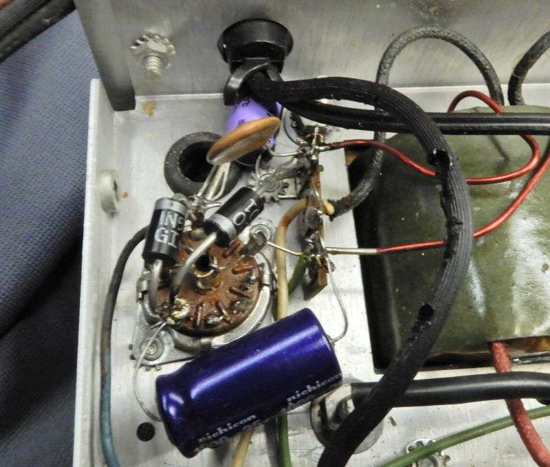
Sometimes when you remove the cover of an amplifier and look inside the phrase "scorched earth" is the first thing that comes to mind.
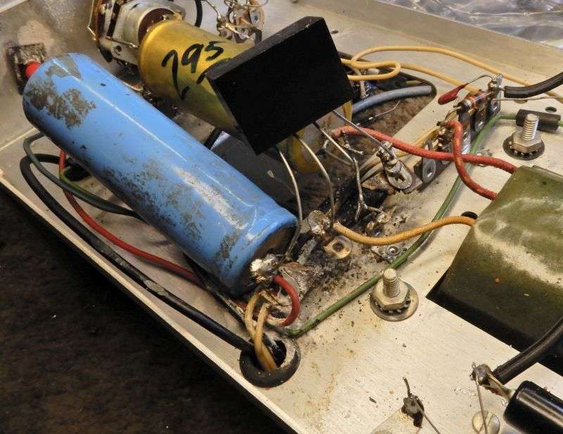
Yes, the brown-bakelite tie strip that supported the bridge rectifier and filter caps has been completely burned away.
I had very little hope for the power transformer, especially after finding a 10-Amp fuse in the fuseholder. But against all odds the power transformer checked okay.
Yee-Ha!
The power transformer is famous for being roached in this model. This guy lucked out big time.
The relay was also a victim of wear and tear, plus a botched attempt to "fix" one circuit.
This provides an incentive to install a 12-Volt DC relay with a transistor keying circuit. The tube-type keyer and relay work okay. If it ain't broke we generally won't fix that. This one was beyond salvation.
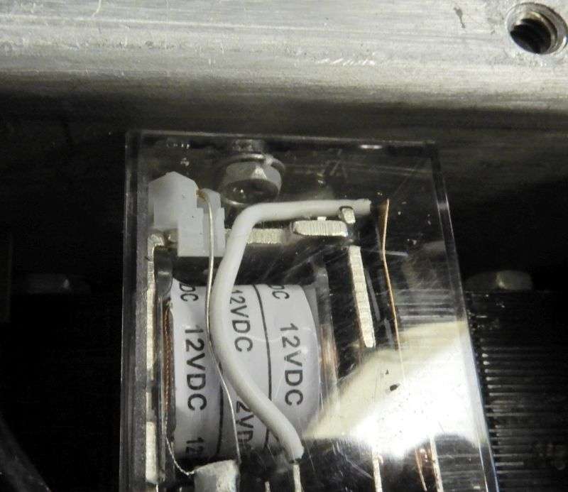
The new relay mounts in one of the original two chassis holes.
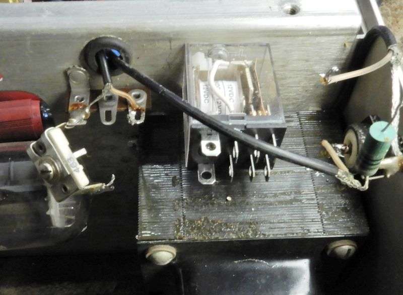
My preferred mounting method is to remove the relay's dust cover, poke a hole in the top, insert a 4-40 screw with tooth washer and snap the dust cover back on. Just choose a spot where the screw head won't interfere with the relay's lever arm.
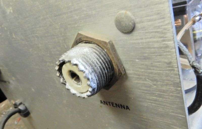
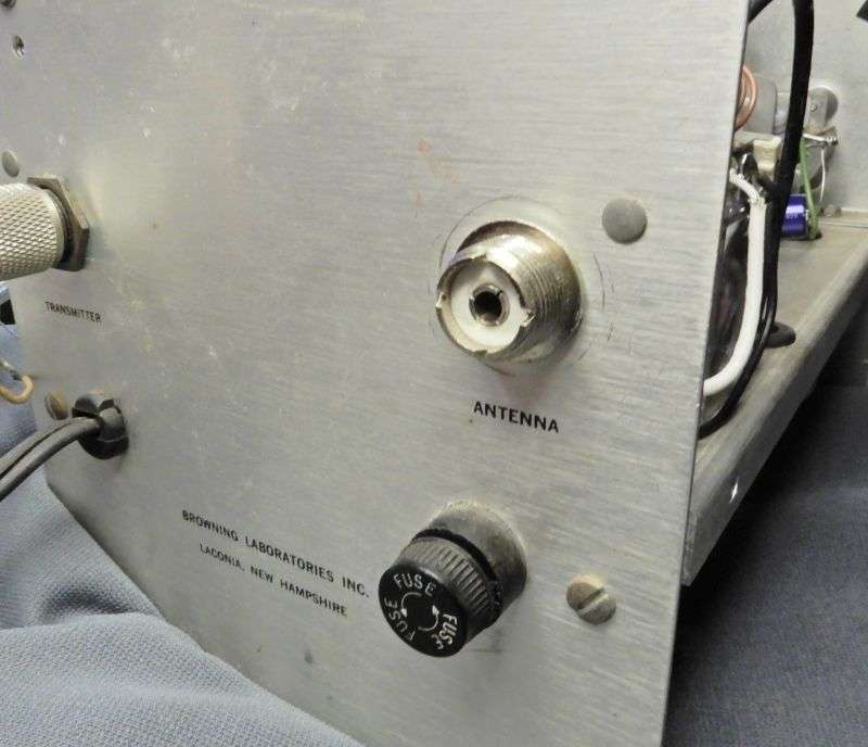
The antenna socket was incredibly crusty. Gotta wonder if the operator of this station knew where the puddle on his desk behind the amplifier was coming from? Pretty sure he had failed to weatherproof the coax at the antenna. Capillary forces will pull any rainwater into the space between the coax jacket and braid. Carries it down into the building. Looks like he didn't have a wattmeter between the amp and the antenna coax.
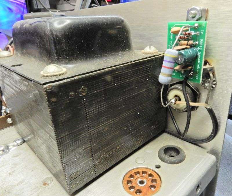
A 12-Volt DC relay needs a source of DC power. The original keying-tube socket is a handy place to mount two rectifier diodes and two electrolytics in a half-wave doubler circuit.
The best place for the new keying circuit is just above the "Radio" socket. A black wire runs over to the relay on the opposite side.
The control grid pin 2 of each tube is grounded in the factory setup. This causes the tubes to run hot, especially if the radio's carrier is turned down. The new keying circuit is more sensitive than the original keying tube, so we don't want the tubes to cherry up and fail if it's operated that way. The pin 2 lug on the right-hand tube is disconnected from its ground wire. A 4.7k 2 Watt resistor and a .01uf disc cap now go from pin 2 to ground .The white wire leads over to pin 2 on the left-hand tube.
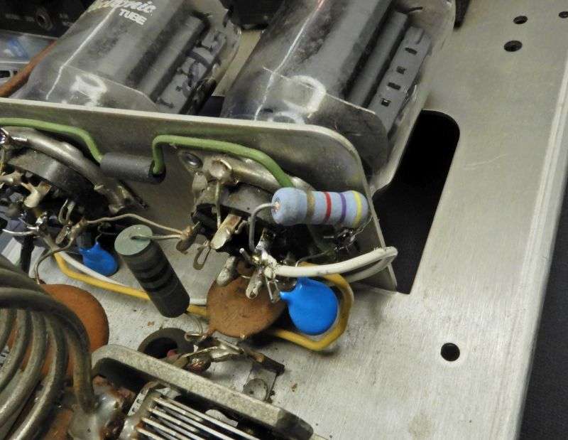
Pin 2 on the left-hand socket also gets the same resistor and disc cap after it's unhooked from its ground wire. The top rectifier diode is "borrowing" the 6.3 Volt AC heater power, feeding into the negative lead of a 1000uf 25 Volt axial cap. The lower diode feeds the negative DC on that filter into the pin 2 lug of the left-hand tube, and through that white wire also to the right-hand tube's grid pin.
The lower diode serves to isolate any negative "grid-leak" voltage that develops on the tubes' grids, so it won't charge up that filter cap. Keeps the bias voltage at a steady negative 8 Volts DC, more or less.
The new relay gets the same slightly-odd hookup as the old one, with the addition of a matching coil to improve the amplifier's 50-ohm match to the radio driving it.
The trimmer cap goes to the relay end of the new coil. The other end of the coil goes to the center conductor of the original coax that leads to the tubes' cathode pins.
You can just make out the bare wire that runs from the hot side of the trimmer cap to the relay lug where the coil connects to it. The green RF choke is there to complete the tubes' cathode circuit to ground when the relay is keyed. This serves to shut down the tubes on standby.
The coil got stretched to miminize the input mismatch, along with the trimmer cap's setting. A coil with one less turn would not have needed to get stretched quite this far. But it worked, so there was no incentive to unwind a turn and try again.
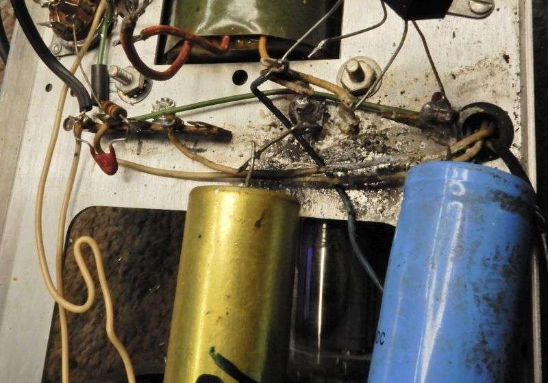
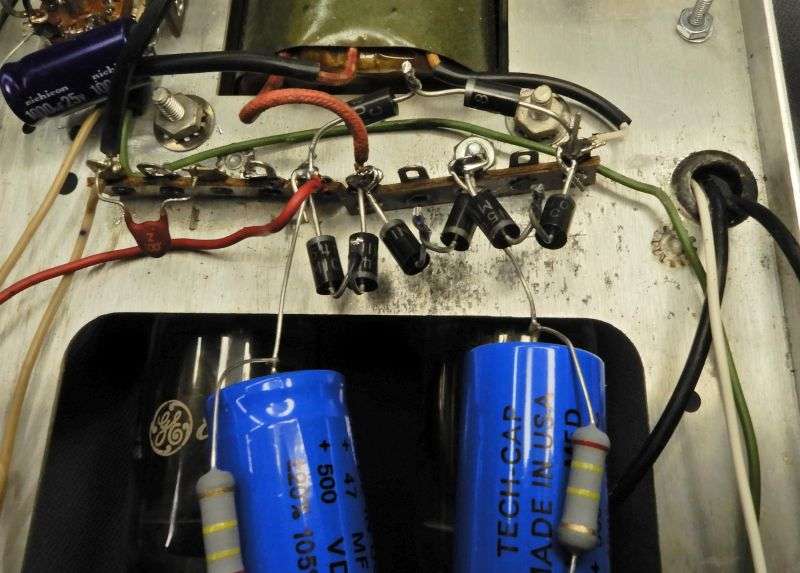
The original epoxy-block rectifier bridge was rated at 1500 Volts. This means it needs two 1N5408 1kV rectifiers for each of the four legs in the bridge circuit. They're cheap, so this does the job, even if it looks a bit odd. Finding 1500-Volt rectifiers is a hassle I don't need, since we buy the 1N5408 500 or a thousand at a time for our other products. The 500-Volt rating on the filter caps is important. Parts rated for 450 Volts won't last long. The 500-Volt parts cost more, but two of them are cheaper than the trouble to string three 450-Volt parts in series.
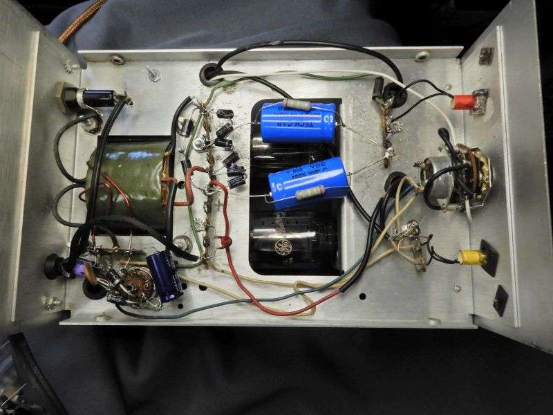
The final result looks halfway decent now. The last detail was to rewire the "Standby" circuit of the power switch. It was originally wired to shut down the high voltage. Since the factory relay was powered from the HV supply, this did the job. Now that switch circuit gets rewired to shut down the 12 Volt DC supply to the new relay.
Oh, and the new antenna socket looks a lot better, too.
This was not a simple or cheap job. But the customer was happy to get it back working. And that's what counts in this business.
73
Yes, the brown-bakelite tie strip that supported the bridge rectifier and filter caps has been completely burned away.
I had very little hope for the power transformer, especially after finding a 10-Amp fuse in the fuseholder. But against all odds the power transformer checked okay.
Yee-Ha!
The power transformer is famous for being roached in this model. This guy lucked out big time.
The relay was also a victim of wear and tear, plus a botched attempt to "fix" one circuit.
This provides an incentive to install a 12-Volt DC relay with a transistor keying circuit. The tube-type keyer and relay work okay. If it ain't broke we generally won't fix that. This one was beyond salvation.
The new relay mounts in one of the original two chassis holes.
My preferred mounting method is to remove the relay's dust cover, poke a hole in the top, insert a 4-40 screw with tooth washer and snap the dust cover back on. Just choose a spot where the screw head won't interfere with the relay's lever arm.
The antenna socket was incredibly crusty. Gotta wonder if the operator of this station knew where the puddle on his desk behind the amplifier was coming from? Pretty sure he had failed to weatherproof the coax at the antenna. Capillary forces will pull any rainwater into the space between the coax jacket and braid. Carries it down into the building. Looks like he didn't have a wattmeter between the amp and the antenna coax.
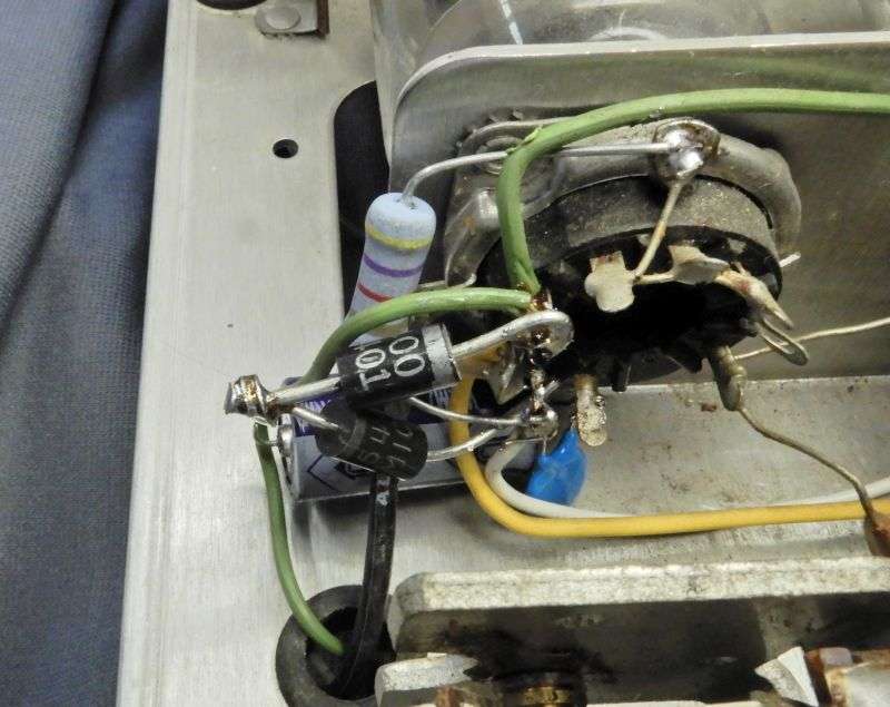
A 12-Volt DC relay needs a source of DC power. The original keying-tube socket is a handy place to mount two rectifier diodes and two electrolytics in a half-wave doubler circuit.
The best place for the new keying circuit is just above the "Radio" socket. A black wire runs over to the relay on the opposite side.
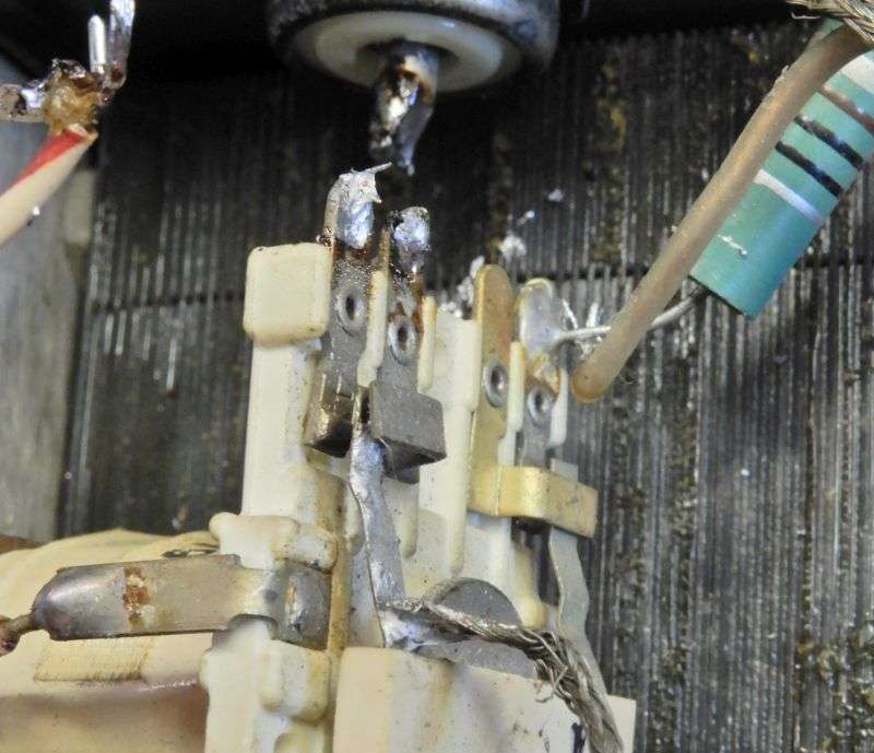
The control grid pin 2 of each tube is grounded in the factory setup. This causes the tubes to run hot, especially if the radio's carrier is turned down. The new keying circuit is more sensitive than the original keying tube, so we don't want the tubes to cherry up and fail if it's operated that way. The pin 2 lug on the right-hand tube is disconnected from its ground wire. A 4.7k 2 Watt resistor and a .01uf disc cap now go from pin 2 to ground .The white wire leads over to pin 2 on the left-hand tube.
Pin 2 on the left-hand socket also gets the same resistor and disc cap after it's unhooked from its ground wire. The top rectifier diode is "borrowing" the 6.3 Volt AC heater power, feeding into the negative lead of a 1000uf 25 Volt axial cap. The lower diode feeds the negative DC on that filter into the pin 2 lug of the left-hand tube, and through that white wire also to the right-hand tube's grid pin.
The lower diode serves to isolate any negative "grid-leak" voltage that develops on the tubes' grids, so it won't charge up that filter cap. Keeps the bias voltage at a steady negative 8 Volts DC, more or less.
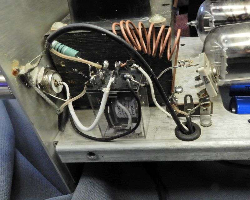
The new relay gets the same slightly-odd hookup as the old one, with the addition of a matching coil to improve the amplifier's 50-ohm match to the radio driving it.
The trimmer cap goes to the relay end of the new coil. The other end of the coil goes to the center conductor of the original coax that leads to the tubes' cathode pins.
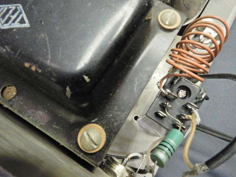
You can just make out the bare wire that runs from the hot side of the trimmer cap to the relay lug where the coil connects to it. The green RF choke is there to complete the tubes' cathode circuit to ground when the relay is keyed. This serves to shut down the tubes on standby.
The coil got stretched to miminize the input mismatch, along with the trimmer cap's setting. A coil with one less turn would not have needed to get stretched quite this far. But it worked, so there was no incentive to unwind a turn and try again.
The original epoxy-block rectifier bridge was rated at 1500 Volts. This means it needs two 1N5408 1kV rectifiers for each of the four legs in the bridge circuit. They're cheap, so this does the job, even if it looks a bit odd. Finding 1500-Volt rectifiers is a hassle I don't need, since we buy the 1N5408 500 or a thousand at a time for our other products. The 500-Volt rating on the filter caps is important. Parts rated for 450 Volts won't last long. The 500-Volt parts cost more, but two of them are cheaper than the trouble to string three 450-Volt parts in series.
The final result looks halfway decent now. The last detail was to rewire the "Standby" circuit of the power switch. It was originally wired to shut down the high voltage. Since the factory relay was powered from the HV supply, this did the job. Now that switch circuit gets rewired to shut down the 12 Volt DC supply to the new relay.
Oh, and the new antenna socket looks a lot better, too.
This was not a simple or cheap job. But the customer was happy to get it back working. And that's what counts in this business.
73
Last edited:
