• You can now help support WorldwideDX when you shop on Amazon at no additional cost to you! Simply follow this Shop on Amazon link first and a portion of any purchase is sent to WorldwideDX to help with site costs.

Browning MKlll Transmitter

238

Active Member
May 20, 2019
146
9
28
77
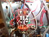
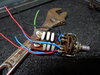
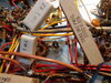
Got a MKlll Transmitter that someone add a kit too that gave them the chs above 23. It is the transmitter that dose not have the ALC pot inside. They take the SWR pot out and put the kit there. you can see it in the pic. They tied the on/off wires together & plug it in to receiver. What i was hunting is the original instructions that came with these kits. The kits where sold by H.F.International Englewood, Ca. I took the kit out of another one i had. The other time i had a stock one sitting next to it. I am not planing on taking this kit out, just wanting to see what they changed. The big switch is going out in this radio, an i am wanting to try an by past it. And wire it for AM only. I know it has been doDSC00868.JPG ne so i want to try it. 238
 
Last edited:

It is the transmitter that has CB/HF/XL
The Mark III sets I have had all had the CB/HF/XTL switch on the receiver. There is a kit to change your receiver to this set up as well. (I assume for the earlier model Mark III receivers that the VFO dial was only labeled Ch.1-23) It comes with a different VFO dial for the receiver.
dose not have the ALC pot inside
I have always assumed that the transmitter contained the ALC circuit. A receiver would/could contain an AGC circuit.

I once had a set of Mark III's that the transmitter was modified for channels above 23 with a push/pull switch on the transmitter mode switch. When pulled, the switch added 3 different crystals (5Mhz range I think)depending on mode (AM,USB or LSB)in to the "mix" of the main channel crystals (16Mhz I think). It worked very well!

Is this what you are asking about? I do not have any instructions for this mod, but am curious as I never knew this was offered as a kit by anyone.

73
David
 
The Mark III sets I have had all had the CB/HF/XTL switch on the receiver. There is a kit to change your receiver to this set up as well. (I assume for the earlier model Mark III receivers that the VFO dial was only labeled Ch.1-23) It comes with a different VFO dial for the receiver.

I have always assumed that the transmitter contained the ALC circuit. A receiver would/could contain an AGC circuit.

I once had a set of Mark III's that the transmitter was modified for channels above 23 with a push/pull switch on the transmitter mode switch. When pulled, the switch added 3 different crystals (5Mhz range I think)depending on mode (AM,USB or LSB)in to the "mix" of the main channel crystals (16Mhz I think). It worked very well!

Is this what you are asking about? I do not have any instructions for this mod, but am curious as I never knew this was offered as a kit by anyone.

73
David
 
I was having a senior moment i reckon when i put the CB/HF/XL in there. That is on the receiver & i am working the transmitter. That broad has 6 crystals on it & has 3 positions on it. The one i removed out of the other transmitter has 2 positions with 6 crystal. I went back an tied to fix my first post. I still got the one i took out. They took the on/off switch out put SWR pot there. Here is a copy of first sheet. 90814580_3078390808878197_5003204220539633664_o.jpg
 
238,
Good info. I never knew there was a kit for this!
If the prior unit you had only had 2 positions, wonder if it was an AM only transmitter? Maybe it was a kit from a different manufacturer?

73
David
 
I have not taken this one loose to look at the topside. I will do that an see if it is the same as other one. My main plan is to figure out how to wire around the big switch & make it for AM only. 238
 
The oscillator circuit where this kit is wired uses three crystals. One for each mode. The AM crystal has only a fixed disc capacitor on it. The USB and LSB crystal each has its own trimmer cap.

Cheap solution was to switch out only the AM crystal to move up or down 23 channels. To get those frequencies for all three modes requires three new crystals for each new band.

Bad news is that this crystal feeds into a terribly narrow-banded tuned circuit T6. It can be peaked for one band only. This will tend to make the other band or bands very weak on transmit. Never saw a convincing way to broadband T6. I do remember one guy who took T6 loose and laid it on its side, glued to the chassis deck. He punched a hole in the face plate to line up with the adjustment hole in T6. Took an extra-long twiddle stick so you could peak the coil in T6 from a knob on the front, attached to the stick.

Change bands, just re peak that knob, like the plate tune on the rear.

Wore out the threads in T6 soon enough.

Had to give the guy credit for imagination, though.

73
 
Dmans here is pics of the kit in the radio. And the one i took out. 238
 

Attachments

  • DSC00006.JPG
    DSC00006.JPG
    2.9 MB · Views: 11
  • DSC00007.JPG
    DSC00007.JPG
    3 MB · Views: 11
Here is a thing they did to this to make a hi/low switch. I was wondering if this effected some thing else in the radio? They added 2 1K resisters in series with the 2000ohm. Then put 2 wires from the ends of the resister too a toggle switch for hi/low. Also put a bulb from the ends of the wires. 238
 

Attachments

  • DSC00019.JPG
    DSC00019.JPG
    2.9 MB · Views: 13
Bit of a hack job.

The brown wires to the switch will totally bypass the resistors that set the AM carrier. Gets you about 8 or 9 Watts of carrier. And a lot less audio. The modulator doesn't have the audio wattage needed to fully modulate a carrier that big. Wattmeter shows more, but your modulation percentage will fall. And that's what the radio at the other end hears, is that modulation percentage. It can't 'hear' the wattmeter.

The two 1k resistors added in series with R49 (the 2000 ohm) should bring the carrier down to a Watt and a half or two Watts more or less. The neon lamps are meant to reduce the voltage drop of the resistors when audio voltage builds up across R49. It's meant to increase forward swing. Only gives the audio a 'gravelly' quality in my experience. Makes the wattmeter a bit more lively on modulation, but sounds terrible.

73
 
I was going to remove the high watt wires for sure. Butt if i leave the resisters in line, but remove the bulb, that still lowers the voltage to the transformer. So i had figured all along i would put it back stock. Have you ever put the kits like you use for low key for sale DIY? 238
 

dxChat
Help Users
  • No one is chatting at the moment.