• You can now help support WorldwideDX when you shop on Amazon at no additional cost to you! Simply follow this Shop on Amazon link first and a portion of any purchase is sent to WorldwideDX to help with site costs.

BUILDING MY FIRST TUBE AMP, ADVICE AND HELP

680MAINE

Member
May 31, 2006
25
2
13
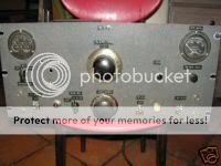
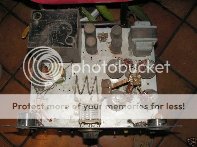
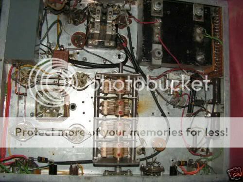
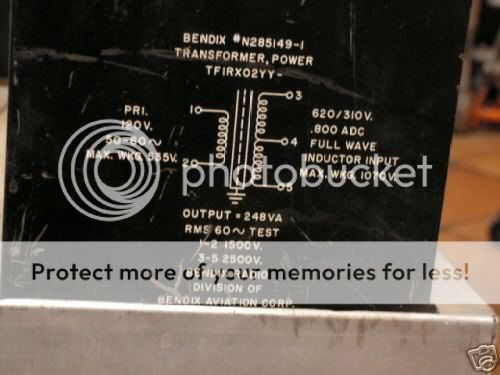
6 YRS AGO i bought a basket case homebrew 4 tube 811a amplifier. Mostly bc I thought it had a cool nostalgia look to it and to rebuild it and mount it in my rack for when I needed those extra watts to make contacts. Well it's been through 2 moves now, severely damaged by one of those moves and is more of a basket case than ever before. Now that I have more time and some extra money o would really like to rebuild it and put it back into service. Here is my dilemma, I have never built/rebuilt a tube amplifier before. I have some experience building mobile amps all the up to a 8pill, but tubes are a whole other animal. I know the basics that high voltage will kill me. So I will be looking for some serious help along the way. I will post detailed pictures so that those that know will be able to help me through it. I'll take some pictures of it and post them so everyone can see what I'm working with.
 
  • Like
Reactions: 1 person

Ok here are some pictures of the amp that I'm going to attempt to rebuild using 572b's instead of the 811a's

front of amp
da_21.jpg


looking down onto the tubes and coils
tubes.jpg


looking at the bottom of the RF deck, there is some rust and corrosions as well as a spot where it looks like the smoke was let out of a resister, there is a brown/burnt looking spot.
plates.jpg


the transformer
f7_12_sb1.jpg


looking at the pl259 plugs and the transformers, tubes, rf deck
back.jpg


I think my first action is to scketch out the schematics of the amp on paper so that I can kinda have an idea as to what is going on and where its going. Or should I just strip the entire RF deck down and start over? SOme of you with more experience take a look at the transformer, Am I seeing this correctly that I could possibly have up to 2500v? Could I go Bigger on my tubes??? If so which ones?
 
I have no clue what it was used for prior to me getting it, it was probably a 11 meter special. Which is fine as I'd like it to be able to cover 6 meters to 20 meters. I occasionally will crank up my power when necessary to make contacts over the yahoos clogging up the airwaves with there non sense, hence why I'd like to resurrect this old relic and put it back into service, plus it'll add nice mood lighting to the shack.
 
Agreed. They can be made to work on 6m but are finicky and the high output capacitance makes it hard to find a plate tuning capacitor small enough to work. 3-500Z's are better if you want the glow of glass.
 
I think my first action is to scketch out the schematics of the amp on paper so that I can kinda have an idea as to what is going on and where its going. Or should I just strip the entire RF deck down and start over? SOme of you with more experience take a look at the transformer, Am I seeing this correctly that I could possibly have up to 2500v? Could I go Bigger on my tubes??? If so which ones?

The most important rating on the transformer is the 248 VA. Volt amps or VA directly equal the rated output wattage of the transformer. Believe it or not, this one is only rated at 248 watts. The good news is most are underrated and can handle more load intermittently. The 2500 volt rating is not the output voltage either. This is the maximum voltage the internal insulation can handle. Otherwise known as the breakdown voltage.
 
The most important rating on the transformer is the 248 VA. Volt amps or VA directly equal the rated output wattage of the transformer. Believe it or not, this one is only rated at 248 watts. The good news is most are underrated and can handle more load intermittently. The 2500 volt rating is not the output voltage either. This is the maximum voltage the internal insulation can handle. Otherwise known as the breakdown voltage.


Yeah i missed that the first time around. Didn't really look at the xmfr pix too well. The xmfr is rated for 800 mA with an output voltage of 310 volts on either side of center tap. That is where the 248 watt (va) rating comes from. 310 volts x 800mA = 248 watts. The xmfr would normally have the center tap grounded and be used with a full wave rectifier however with the insulation rated for 2500 volts it may be possible to use a bridge rectifier and take the ouput voltage directly across pins 3 and 5 to get 620 volts. Either way the VA rating is too light for much power.
 

dxChat
Help Users
  • No one is chatting at the moment.
  • @ Wildcat27:
    Hello I have a old school 2950 receives great on all modes and transmits great on AM but no transmit on SSB. Does anyone have any idea?
  • @ ButtFuzz:
    Good evening from Sunny Salem! What’s shaking?
  • dxBot:
    63Sprint has left the room.
  • dxBot:
    kennyjames 0151 has left the room.