• You can now help support WorldwideDX when you shop on Amazon at no additional cost to you! Simply follow this Shop on Amazon link first and a portion of any purchase is sent to WorldwideDX to help with site costs.

Carrier VS. Swing on AM...

Status
Not open for further replies.

ExitThirteen

Grumpy and Cranky
Apr 18, 2008
1,968
1,678
173
Cornpatch of Iowa
I have a question about AM carrier (deadkey) VS. swing (modulated) output. What is true 100% modulation for AM? Is it double the carrier (ie. 4W swinging to 8W) or is it 4 times the carrier (ie. 4W swinging to 16W)? I've heard so many conflicting stories, even the local ham guys are divided up on this one. What's the real deal here? Is it 2x the carrier, or 4x the carrier? Would like to get more of a concrete answer. Thanks in advance!


~Cheers~
 

Four times the carrier will get you in the ball park. The best method to set 100% modulation is using an O scope.
 
That was always my understanding of it... you had to have about 4x the carrier to get 100% modulation. And I agree, best to set it up using a good oscilloscope (which I do have). (y)


~Cheers~
 
Four times the carrier will get you in the ball park. The best method to set 100% modulation is using an O scope.
"Ballpark" is exactly right. Setting the carrier to modulate 1.5x for average, and 4x for pep is only one element, setting the modulation is yet another.
 
The proper ratio is four times the power or something like 4 watts peaking to 16 watts. I think where some people get confused about the 2 times or 4 times thing is that when looking at an oscilloscope you want to see twice the carrier on the screen. That is because the scope reads RF voltage and twice the voltage into a constant load (antenna) is also twice the current and twice the current along with twice the voltage is four times the power.
 
It depends on how and where you are measuring power.
To simplify things lets deal with only the '+' half cycle of a signal. (The same applies to the '-' half cycle.)
100% modulation means that enough signal (modulation) is applied to a non-varying signal (carrier) so that the resulting combination equals to either twice the power of the carrier or zero power. That corresponds to the 90 and 180 degree points of that combined signal and equals 100% modulation of that non-varying signal. If the carrier is 10 watts and the modulation signal is 10 watts then the result of their addition is either '0' watts of 20 watts. That's 100% modulation of the carrier by the applied modulation signal.
The exact same thing applies to the '-' half cycle of that AC signal combination. The power being measured at the outputs of the carrier oscillator and the applied modulation oscillator. That means that the modulation and the carrier are the same power levels. If you measure the combined signals with a watt meter then it's two times the output of either carrier or modulation.
Ah! But this is AC, right? Both a '+' and a '-' half cycle. And since the '-' half cycle is exactly the same as the '+' half cycle, the ratio of carrier and modulation is still 1:1, but if measured by an oscilloscope, then that ratio changes to 2:1 because of the way that oscilloscope displays things. That's where a lot of confusion comes in. The 'catch' is that people think that modulated signal is 4 times the carrier power. It isn't, it's still just 2 times that carrier power. The modulated signal is twice the 'height' of the carrier on the display, but then, the carrier is also twice it's original 'height' (the measured power at the carrier oscillator output) so the ratio of modulation to carrier is still 1:1. It's just displayed differently. That means that the one doing that measuring doesn't know how that oscilloscope works, what it's measuring and how. If you don't know how it works it's very easy to think that the modulation is 4 times the power of the carrier, since that's what that o'scope seems to be displaying.
All that is true in a 'perfect' world where there's no resistance or reactance in a circuit. Since there's always some resistance/reactance to overcome, then you have to make a few compromises. Meaning that the applied modulation is typically slightly less power than the carrier to keep things from exceeding that 100% limit.
Since very few people have an oscilloscope and do that measuring with a watt meter, then a 2:1 ratio is what you are looking for.
- 'Doc
 
  • Like
Reactions: 1 person
Hello Folks
New to this group so hope you all can help me out I was doing a search for oscilloscope cause I’m needing to buy a schematic & parts list for the bk precision model 1541A oscilloscope all help will be appreciated Thanks All
 
I just put it on my trusty old meter and tune for a good peak reading and im done....
I dont own a scope and i never will....
 
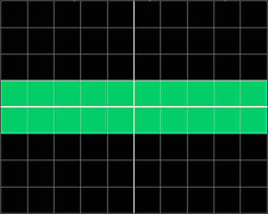
This is an unmodulated carrier:

figure-6.jpg


This is actually a sine wave, but it's oscillating at such a high frequency that on this oscilloscope display, all the lines bleed together and look like a single bar. (If you have a decent oscilloscope, you can crank up the timebase knob until it looks like a sine wave again.) The center horizontal line is 0 volts. The carrier rises to one division above 0 volts and drops one division below 0 volts.

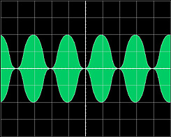
This is a 100% modulated carrier:

figure-8.jpg


The modulating signal is also a sine wave. This is what your output signal looks like when you whistle into the mic.

Notice that here, the positive and negative voltages now extend 2 divisions from the 0 volt line instead of one.

Now let's do the math. Ohm's law says voltage equals current times resistance:

V = IxR

Also, power (in watts) is equal to voltage times current:

P = VxI

Let's choose some simple numbers.

Let's say that our load is 50 ohms (because it usually is).

Let's also say that each full division on the scope is 10 volts.

From Ohm's law, we can calculate that with a 10 volt drop across a 50 ohm load, the current through the load is 0.2 amps (10/50). This yields an output power of 2 watts (0.2x10). That's our carrier power.

Now, if one division is 10 volts, then at 100% modulation, the voltage is doubled. So at a positive modulation peak, there would be 20 volts across the 50 ohm load. Notice that the load remains constant: your antenna should always present a 50 ohm load. (Unless maybe if you dump 10,000 watts into it and it melts.)

Now, Ohm's law tells us that with 20 volts across a 50 ohm load, we have 0.4 amps of current (20/50). This yields an output power of 8 watts (0.4x20).

So the output power on a modulation peak is 4 times that of the carrier.

You don't maintain a peak all the time though: the output varies over time, with the amplitude of the modulation signal. Usually that's your voice. With the sine wave test waveform used in this example, we can calculate average power by dividing by the square root of 2, or 1.414. That yields about 5.6 watts average power.

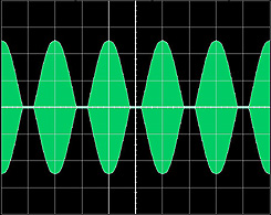
Now, if you over-modulate, you get this:

figure-9b.jpg


Notice that the positive peaks extend a little more than 2 divisions from the 0 volt line, and the negative peaks are flattened out against the 0 volt line. Those flat valleys are where your carrier is totally pinched off. That flattened waveform is a form of distortion, and distortion causes bleed over. If you crank the modulation up even higher, the positive peaks will flatten out too (when you exceed the transmitter's output capacity). Then the modulated signal will look almost like a square wave. That's where you get the worst distortion and the most bleed over.

-Bill
 
Last edited:
  • Like
Reactions: 1 person
I say who cares as long as your getting out. Why worry about all the technical crap?
 
Status
Not open for further replies.

dxChat
Help Users
  • No one is chatting at the moment.