• You can now help support WorldwideDX when you shop on Amazon at no additional cost to you! Simply follow this Shop on Amazon link first and a portion of any purchase is sent to WorldwideDX to help with site costs.

Channels? M58473P PLL

Simbalage22

Active Member
Jul 8, 2010
180
1
26
40
Detroit MI
Hi, My royce has a M58473P PLL in it. According to documentation I have found it says

Take pins 6 and 5 of PLL1 high (7.27v) for more frequencys.

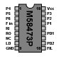
I dont understand what they are referring to, and what the outcome (Gain in channels would be) If I were looking at pin 5 and 6 (I found a diaram) what would I do to get the extra channels? My cobra already has them and i'd like to match a mobile just for when its needed!


Thanks... in advance
 

whats the voltage on pin 1?

i believe its saying you switch pin 1 to pins 5 and 6. i know the pll is very limited on the coverage, it tops out at 27.575
 
whats the voltage on pin 1?

i believe its saying you switch pin 1 to pins 5 and 6. i know the pll is very limited on the coverage, it tops out at 27.575

Next to nothing (see post below) pin 18 is carrying the voltage on this particular pll.. Usually they say tie one to another, pull to ground, cut trace ect.. this is weird because I dont know if they want both 5&6 tied to 7.2v or if tieing 5 and 6 with 2 different switches to 7.2 makes the frequencies..


Original before editing with the above
I am trying to get different channels then the 40 that everyone and their momma is on... and have them reserved in extreme situations... so I would need a double throw switch to send that 7.2v to both 5 and 6 or 2 switches and that would make up the uppers and lowers?
 
Last edited:
Royce channels

Ok 1 has like nothing...

18 which is VCC is at 6.00V DC.....


Pin Name Description
1 P4 Programmable input 4
2 P5 Programmable input 5
3 P6 Programmable input 6
4 F in VCO Frequency Input
5 RI Referency oscillator Input
6 RO Referency oscillator Output
13 NC No Connection
7 LD Loock Detector Output - Locked=LOW Unlocked=HIGH
9 GND Ground
10 FIL
11 PD2 Phase Detector Output 2
12 Connect to Vcc
11 PD1 Phase Detector Output 1
12 Connect to Vcc
15 P1 Programmable input 1
16 P2 Programmable input 2
17 P3 Programmable input 3
18 Vcc Positive Supply Voltage

Although I dont want to change the subject (I AM DETERMINED to get this working like it is) could this pll be changed? if so to what? and those devices they have that you put inline with the pll to get 250 channels would this be best? are they expensive? But INITIALLY I still want info on the original question... just threw this out there for someone that maybe cant answer that one, but knows more about changing plls or boxes ect...

UPDATE: For trial and all other purposes intended.. I tried connecting pins 5 and 6 to 18 which is carrying 6.0v.. either combination (5 to 18 or 6 to 18, Even 5&6 together tied to 18) makes the units meter fail to show its transmitting.. I do however see a change in backround noise on receive.. but turning the switches on the 142 up down ect... and going on the respective channels on the royce with no result... if its right shouldnt it work like the base does? Till I get a response back, I will leave the wires as they are as they were complicated to get 5,6 that close without them actually touching with its board being verticle..
 

Attachments

  • m58473.jpg
    m58473.jpg
    12.2 KB · Views: 62
Last edited:
do not wire voltage to the oscillator input you could damage your radio.
when you attempt to add extra channels to your radio you should only wire the vcc voltage through switches to the programmable input pins. 1, 2, 3, 15, 16, 17.
Also when you do achieve extra channels they will not be in the right order.
there are 6 program pins so 2x2x2x2x2x2 is 64-40 stock channels= 24 extra channels so you will not have many high or low channels unless you have installed a crystal switching kit which are rare. search this forum for buttfuzz's site he has many mods which help to understand what you are doing. You could damage your radio if you proceed any farther. best leave it to an experienced technician.

Thanks for the info.. I am not new to electronics, nor cb, just taking it to a step further then basic tune-ups. I knew something wasnt right on pins 5.6 like the tuneup sheet says so thats why I immediatly stopped. to break a radio and learn a lifetime of knowlege.. Priceless :) So that'd be 6 switches wow :)
 
Ok 1 has like nothing...

18 which is VCC is at 6.00V DC.....


Pin Name Description
1 P4 Programmable input 4
2 P5 Programmable input 5
3 P6 Programmable input 6
4 F in VCO Frequency Input
5 RI Referency oscillator Input
6 RO Referency oscillator Output
13 NC No Connection
7 LD Loock Detector Output - Locked=LOW Unlocked=HIGH
9 GND Ground
10 FIL
11 PD2 Phase Detector Output 2
12 Connect to Vcc
11 PD1 Phase Detector Output 1
12 Connect to Vcc
15 P1 Programmable input 1
16 P2 Programmable input 2
17 P3 Programmable input 3
18 Vcc Positive Supply Voltage

Although I dont want to change the subject (I AM DETERMINED to get this working like it is) could this pll be changed? if so to what? and those devices they have that you put inline with the pll to get 250 channels would this be best? are they expensive? But INITIALLY I still want info on the original question... just threw this out there for someone that maybe cant answer that one, but knows more about changing plls or boxes ect...

UPDATE: For trial and all other purposes intended.. I tried connecting pins 5 and 6 to 18 which is carrying 6.0v.. either combination (5 to 18 or 6 to 18, Even 5&6 together tied to 18) makes the units meter fail to show its transmitting.. I do however see a change in backround noise on receive.. but turning the switches on the 142 up down ect... and going on the respective channels on the royce with no result... if its right shouldnt it work like the base does? Till I get a response back, I will leave the wires as they are as they were complicated to get 5,6 that close without them actually touching with its board being verticle..
Pin 14 is the one you want, it switches the internal code converter giving two sets of N codes, with pin 14 low you get N codes 203 to 329 and high gives N codes of 147 to 210. So assuming that the high setting is normal then putting the pin low instead will move all your channels up by 560Khz or 50 channels. If pin 14 was already low then pulling it high will shift everything down 560Khz.

Dave

Cool... appreciate the feedback, to avoid any kinda confusion what switch config would I use to get channels? a single pole switch to??? the voltage is at 6v so your saying throw more power to it will give more channels? any info on how I would put a switch to get any additional channels would be awsome :)
 
I am not all that knowledgeable about electronics either, I just happen to have some electrical experience from working on tractors. Incidentally the 4 clutchpacks in a deutz agrotron are binary programmable in just the same way as your cb. Each clutchpack has two speeds corresponding to when a wire going to the clutchpack is switched on or off which gives a total of 2x2x2x2= 16 electrically selectable gear ratios. I heard of a farmer wiring into one of the clutchpacks to override the stock programming and the machine did 50mph on the road.
The pll chip in the cb divides frequency ratios to produce a certain frequency in the same way that the tractor divides speed ratios to produce a certain speed.
There are other problems though if you want to learn more you could try some of lou franklin's books (you may inspect them on google books)
as there are issues such as broadbanding and padding the vco that I know little about.

I just posted a thread asking about that book LOL.. I am interested because i am getting some reponses about the voltage, and then about the programable inputs so I am all ears and willing to try different combinations as the worse should happen is I fry the pll or cb all in all giving me a greater challange :)
 
the current going to a program pin is either on or off so to change the pins state you will have to use a three position switch one state for pin current on one state for pin current off and one state for closed circuit
you would have to cut the correct trace and wire the common leg to the pll program pin and one other to vcc and the other to the other side of the trace(edit and another not wired at all). also a resistor would be a good idea as voltage spikes may kill the pll.
Have a read of what I mentioned as you should never be in too much of a rush to blow up your radio. Anytime one lifts the covers you run that risk and it doesn't matter how good you are.
there is a pdf on eproms by martin pickering on the net you could search for and read and also any ham article on 10 meter or 12 meter cb conversion usually cover all the same mods.
 
Last edited:
the current going to a program pin is either on or off so to change the pins state you will have to use a three position switch one state for pin current on one state for pin current off and one state for closed circuit
you would have to cut the correct trace and wire the common leg to the pll program pin and one other to vcc and the other to the other side of the trace. also a resistor would be a good idea as voltage spikes may kill the pll.
Have a read of what I mentioned as you should never be in too much of a rush to blow up your radio. Anytime one lifts the covers you run that risk and it doesn't matter how good you are.
there is a pdf on eproms by martin pickering on the net you could search for and read and also any ham article on 10 meter or 12 meter cb conversion usually cover all the same mods.

I like you! and I dont mean that in a gay way.. Alot of people are so stuck on themself like they never started tinkering and never blew nothing up.. Its more of a learning experience for me as I didnt pay nothing for that 1977 Royce... No one likes to blow them up, but sometimes experimentation is how we learn. I cant count how many xbox's and ps2 I have burned up trial and error, but now I built a pic programmer and can use a board even if the drive is dead and the password is lost.. just read it from eeprom.,,, But yea I will try this later and post results.. I like the idea of 1 or 2 switches VS 6 or so.... So if this actually works. Whoa momma i am gonna be happy :)
 
Pin 14 or 6 switches..Advanced ppl help me....

On one hand I have information to use pin 14 and pull it high or low to shift frequencies, and another telling me to use the 6 program pins to pin 14.. Which is technically correct? If I were to do the pin 14 high/low how would this be accomplished.. As in is it high now (6.0v) or low? and if it need be one or the other how would this be done... if I clip the voltage to it completly wouldnt that yeild the chip not getting power at all or functioning?
 
Cool... appreciate the feedback, to avoid any kinda confusion what switch config would I use to get channels? a single pole switch to??? the voltage is at 6v so your saying throw more power to it will give more channels? any info on how I would put a switch to get any additional channels would be awsome :)
You simply make sure pin 14 is isolated from everything else, then connect a 10k resistor one end to pin 4 and the other end to pin 9 (gnd). Now take a single pole single throw switch and connect the centre pin to pin 14 then say the lower pin to pin 9 and the upper pin to pin 18, done! fodendaf said you need a 3 position switch, you don't! Pin 14 is not tristate, it is either high (6v) or low (0v).
Note that when pin 14 is low the channels will be spaced 20Khz apart not 10Khz.

Dave
 
Last edited:
You simply make sure pin 14 is isolated from everything else, then connect a 10k resistor one end to pin 4 and the other end to pin 9 (gnd). Now take a single pole single throw switch and connect the centre pin to pin 14 then say the lower pin to pin 9 and the upper pin to pin 18, done! fodendaf said you need a 3 position switch, you don't! Pin 14 is not tristate, it is either high (6v) or low (0v).

Dave

MUCH APPRECIATED!!! Sorry for the caps but this is what I was after.. Will give it a try.. Thats what I wanted to know the high and low... so I just need one switch and a resistor? Also was looking into building/buying a EXPANDER 240 are they easy to get? So basically adding/dropping the voltage on 14 will make the channels? on being legal 40 and off going what direction? I am going to try your instructions to a tee.. Being spoonfed is nice when learning, but i am trying to learn what I am doing for future reference too :)
EDIT: when you say isolate, you mean cut the trace so its not connected to anything on the board but what you are describing?
 

dxChat
Help Users
  • No one is chatting at the moment.