
The Cobra 148 has now been built by a dozen vendors, with a variety of different main circuit boards, and different control/front panel switch arrangements.
There is no "universal" procedure that's correct across all production changes and vendors.
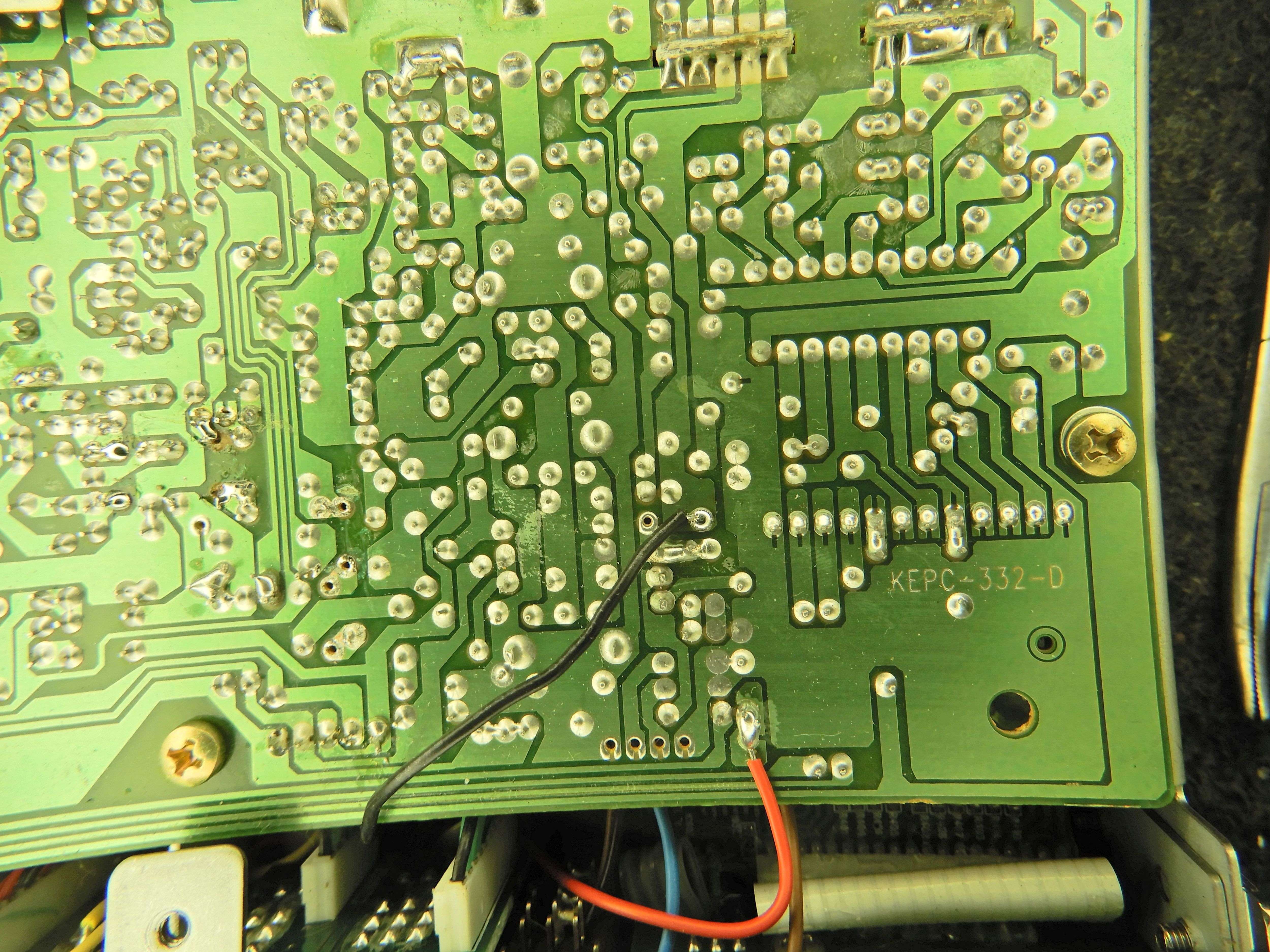
So here is just one of them. This radio is a Cobra 148NWST. Forgot the production date, but the main pc board is identified as "KEPC-332-D". Plenty of Cobra 148 radios were built from this pc board, but not all of them by any stretch.
The Uniden circuit board and the early 1990s Malaysia board are nearly identical to each other, but WAY DIFFERENT from this one.
With any luck we'll see one of those in the near future and get pics of the same process, but with the layout differences taken care of. Here is the setup to "lock" the clarifier's transmit frequency to the receiver frequency. The factory setup "splits" these, with the clarifier connected in receive only. Your transmit frequency is set by a trimmer pot inside the radio. "Locking" them together simplifies a conversation with more than one sideband station at a time, with all of them transmitting clarified to the same slot.
In any CB like this there are three basic steps.
First, remove the source of transmit-only power from the original trimpot.
Second, remove the source of receive-only power from the front-panel clarifier control.
Third, power the clarifier from a steady source that's always on for both receive and transmit.
In this radio, the transmit-only source gets disabled by removing one or the other of two diodes, D52 and D75. No need to unhook more than one. No need to do more than unsolder one leg, and lift it above the circuit board surface. If somebody wants to put it back later, there it is.
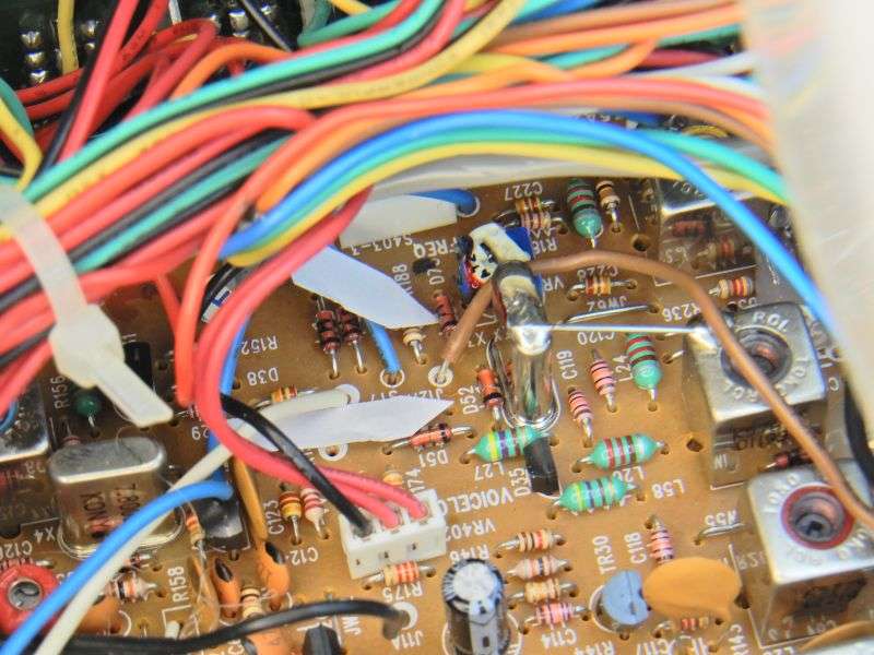
Yes, I know. Neither one has been disconnected in the pic. Figure it out.
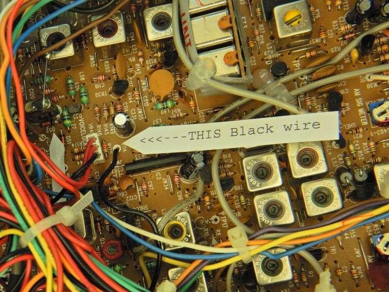
Next we need to find a black wire that powers the front-panel clarifier control. The one we want is here, soldered to a hole marked "J11A". Don't take it loose, this step simply identifies the wire so you can follow it to the other end.
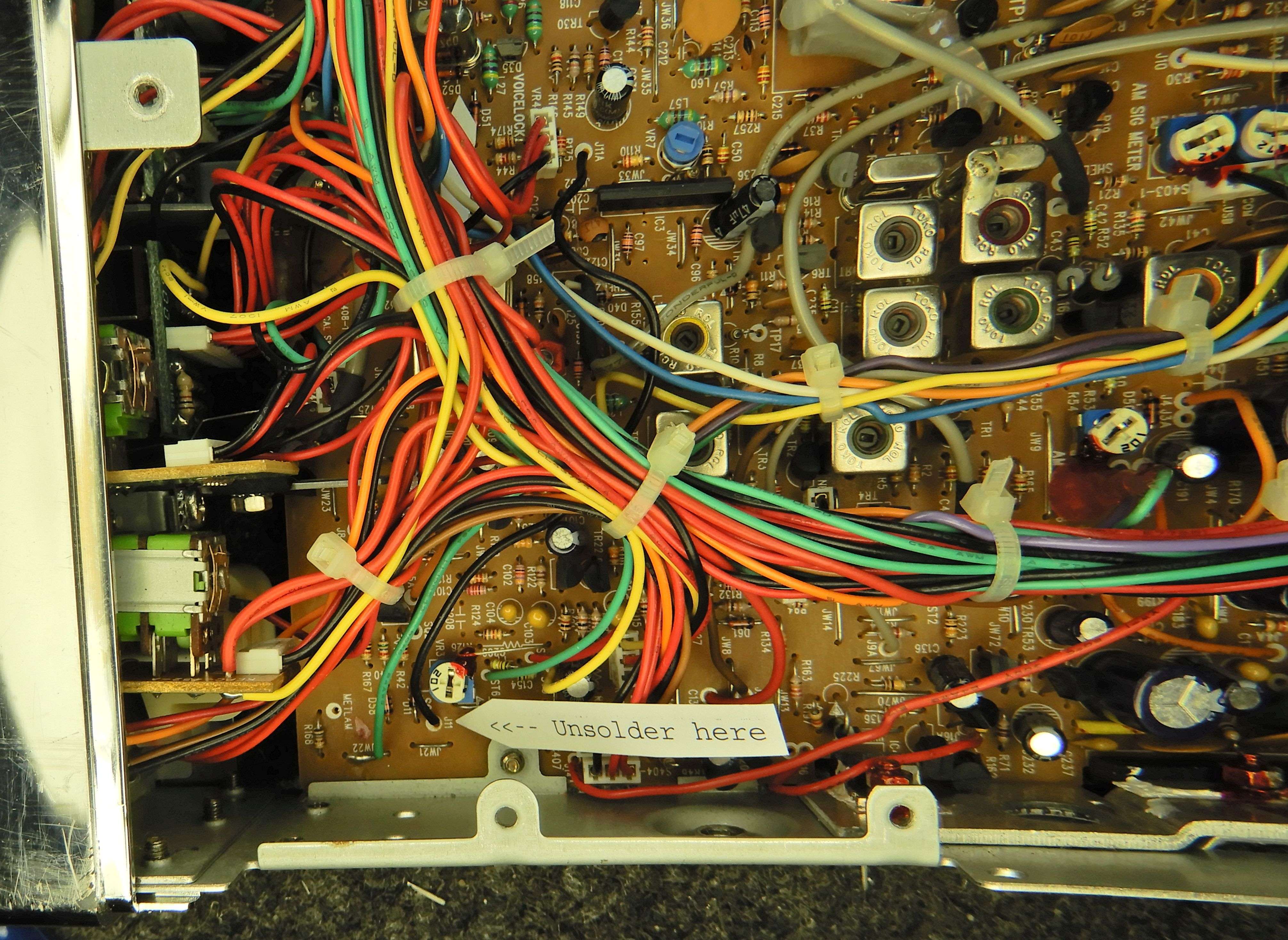
The other end of the black wire teminates at a spot marked, oddly enough "J11". Unsolder this end of the wire and feed it around the front edge of the circuit board to the solder side.
This is the easiest spot to obtain 8 Volts DC for the loose end of the black wire.
This mod should not disturb the previous adjustment of the clarifier's receive frequency. This will reduce the complaints that you are transmiting "off frequency" from the soreheads that didn't want to turn their clarifier knob every time a different station keys up.
73
There is no "universal" procedure that's correct across all production changes and vendors.
So here is just one of them. This radio is a Cobra 148NWST. Forgot the production date, but the main pc board is identified as "KEPC-332-D". Plenty of Cobra 148 radios were built from this pc board, but not all of them by any stretch.
The Uniden circuit board and the early 1990s Malaysia board are nearly identical to each other, but WAY DIFFERENT from this one.
With any luck we'll see one of those in the near future and get pics of the same process, but with the layout differences taken care of. Here is the setup to "lock" the clarifier's transmit frequency to the receiver frequency. The factory setup "splits" these, with the clarifier connected in receive only. Your transmit frequency is set by a trimmer pot inside the radio. "Locking" them together simplifies a conversation with more than one sideband station at a time, with all of them transmitting clarified to the same slot.
In any CB like this there are three basic steps.
First, remove the source of transmit-only power from the original trimpot.
Second, remove the source of receive-only power from the front-panel clarifier control.
Third, power the clarifier from a steady source that's always on for both receive and transmit.
In this radio, the transmit-only source gets disabled by removing one or the other of two diodes, D52 and D75. No need to unhook more than one. No need to do more than unsolder one leg, and lift it above the circuit board surface. If somebody wants to put it back later, there it is.
Yes, I know. Neither one has been disconnected in the pic. Figure it out.
Next we need to find a black wire that powers the front-panel clarifier control. The one we want is here, soldered to a hole marked "J11A". Don't take it loose, this step simply identifies the wire so you can follow it to the other end.
The other end of the black wire teminates at a spot marked, oddly enough "J11". Unsolder this end of the wire and feed it around the front edge of the circuit board to the solder side.
This is the easiest spot to obtain 8 Volts DC for the loose end of the black wire.
This mod should not disturb the previous adjustment of the clarifier's receive frequency. This will reduce the complaints that you are transmiting "off frequency" from the soreheads that didn't want to turn their clarifier knob every time a different station keys up.
73
