
Hi All,
I hope all is well and was hoping to get some feedback from the forum for a new antenna project I am working on. I've been attempting to learn all I can about vertical collinear antennas and the various methods of loading and phasing them. I want to avoid a jpole design due to the extra space wasted by the j-match section, their issues with common-mode and just based on mediocre results obtained by the j-poles I have used, including a copper standard j-pole, a twin-lead j-pole in PVC and finally a twin-lead super j-pole collinear in PVC. I found that my 5/8 wave Comet vertical dominated all of those, including the super-j which was supposed to have higher gain on paper.
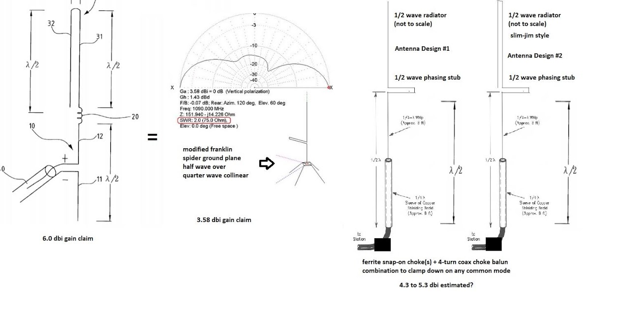
I came across an interesting collinear design in Google patents, as shown below in the first antenna diagrammed on the left. It appears to be a center-fed dipole at the base which is co-phased in series with a coil matching section and an upper half-wave parallel radiator element that closely resembles a slim jim. They claim 6dbi gain in the patent, which is questionable because they appear to add extra mythical slim jim gain simply because of the folded vertical element on top.
The closest thing I could find in practice was a so-called "Franklin Spider" ground plane antenna. It uses a half wave matching stub instead of a series coil, substitutes radials for the single ground dipole element and lacks the slim jim top. They claim 3.58dbi gain for that one. I live in an HOA and want to avoid radials, opting for a slim low profile vertical antenna mounted to a discreet tall fiberglass rod. My design keeps the center-fed dipole like the original patent at the base, but I elected to use a coaxial sleeve dipole arrangement to keep that clean vertical profile.
The sleeve portion is 3/4" aluminum tube with thin RG174 coax inside being choked off by the sleeve and tied to the coax ground at the top of the element. I plan on adding some clamp on ferrites at the base of the sleeve/top of the feedline to fight common mode. I plan on opting for the 1/2 wave tuning stub hairpin like the franklin design due to simplicity to feed the top half wave element. I'd do a coil to increase element spacing, but there's no easy guidance on how to do that correctly. The patent just says it uses a coil less than a 1/4 wavelength in height. I'm debating whether to use a standard 1/2 wave top element or modifying it to the folded slim jim style of the original patent.
I'm open to thoughts on the design in general, whether to use the standard or folded top element, etc. I'd be especially grateful if there are any NEC wizards out there willing to model these. I haven't settled on a single design direction yet because I don't want to waste materials or deal with multiple dangerous trips on and off our steep roof. I've seen so many super jpole designs out there which are basically stacked 1/2 wave elements, but with the bottom element being end-fed with a 1/4 wave j-match. I've yet to find any that substitute a center-fed half--wave dipole for the bottom 1/2 wave element.
In my mind, in the coaxial dipole arrangement, you save dealing with the j-match and save a 1/4 wavelength of wasted mast space. I plan on using 75 ohm coax to feed it, which would match the dipole driver section nicely. This also adds a ground element via the lower dipole sleeve section, which would hopefully fight the feedline coupling problem from jpoles. I just don't know if I am looking at this wrong. I'm having trouble visualizing the waveform/phase relationship of all the elements between the end-fed and base of a jpole or a center-fed dipole. Your thoughts are appreciated. Once a design option is settled upon, I look forward to building it and sharing the results with the forum. Thanks!
-Nick
I hope all is well and was hoping to get some feedback from the forum for a new antenna project I am working on. I've been attempting to learn all I can about vertical collinear antennas and the various methods of loading and phasing them. I want to avoid a jpole design due to the extra space wasted by the j-match section, their issues with common-mode and just based on mediocre results obtained by the j-poles I have used, including a copper standard j-pole, a twin-lead j-pole in PVC and finally a twin-lead super j-pole collinear in PVC. I found that my 5/8 wave Comet vertical dominated all of those, including the super-j which was supposed to have higher gain on paper.
I came across an interesting collinear design in Google patents, as shown below in the first antenna diagrammed on the left. It appears to be a center-fed dipole at the base which is co-phased in series with a coil matching section and an upper half-wave parallel radiator element that closely resembles a slim jim. They claim 6dbi gain in the patent, which is questionable because they appear to add extra mythical slim jim gain simply because of the folded vertical element on top.
The closest thing I could find in practice was a so-called "Franklin Spider" ground plane antenna. It uses a half wave matching stub instead of a series coil, substitutes radials for the single ground dipole element and lacks the slim jim top. They claim 3.58dbi gain for that one. I live in an HOA and want to avoid radials, opting for a slim low profile vertical antenna mounted to a discreet tall fiberglass rod. My design keeps the center-fed dipole like the original patent at the base, but I elected to use a coaxial sleeve dipole arrangement to keep that clean vertical profile.
The sleeve portion is 3/4" aluminum tube with thin RG174 coax inside being choked off by the sleeve and tied to the coax ground at the top of the element. I plan on adding some clamp on ferrites at the base of the sleeve/top of the feedline to fight common mode. I plan on opting for the 1/2 wave tuning stub hairpin like the franklin design due to simplicity to feed the top half wave element. I'd do a coil to increase element spacing, but there's no easy guidance on how to do that correctly. The patent just says it uses a coil less than a 1/4 wavelength in height. I'm debating whether to use a standard 1/2 wave top element or modifying it to the folded slim jim style of the original patent.
I'm open to thoughts on the design in general, whether to use the standard or folded top element, etc. I'd be especially grateful if there are any NEC wizards out there willing to model these. I haven't settled on a single design direction yet because I don't want to waste materials or deal with multiple dangerous trips on and off our steep roof. I've seen so many super jpole designs out there which are basically stacked 1/2 wave elements, but with the bottom element being end-fed with a 1/4 wave j-match. I've yet to find any that substitute a center-fed half--wave dipole for the bottom 1/2 wave element.
In my mind, in the coaxial dipole arrangement, you save dealing with the j-match and save a 1/4 wavelength of wasted mast space. I plan on using 75 ohm coax to feed it, which would match the dipole driver section nicely. This also adds a ground element via the lower dipole sleeve section, which would hopefully fight the feedline coupling problem from jpoles. I just don't know if I am looking at this wrong. I'm having trouble visualizing the waveform/phase relationship of all the elements between the end-fed and base of a jpole or a center-fed dipole. Your thoughts are appreciated. Once a design option is settled upon, I look forward to building it and sharing the results with the forum. Thanks!
-Nick

