

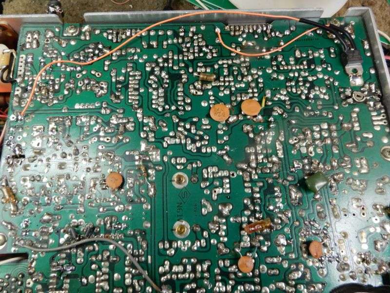
Here's a before picture of the carrier oscillator section in a Cobra 138XLR mobile CB. The X1 socket is empty because the crystal died. Finding a 48 year-old replacement can probably be done, but I'm going a different route. This issue keeps coming up, and I have tired of looking under rocks for crystals just to do a repair.
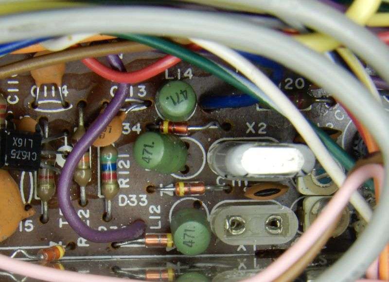
The X1 crystal supplies the 7.8025 MHz carrier for AM transmit and USB receive/transmit both. Now the arithmetic may sound wrong. The crystal filter's center frequency is 7.800 MHz. Placing the crystal frequency above it should generate a lower sideband, right? Not in this case. The radio's local oscillator is 7.8 MHz above the channel frequency. When the 7.xx MHz carrier frequency goes up, the difference between the two frequencies goes down. This causes the sideband to be inverted. A lower sideband going through the 7.8 MHz crystal filter becomes the upper sideband after we mix it with the 35 MHz PLL's output.
This radio uses the USB carrier crystal for the AM carrier, as well.
I have shown the ProgRock module from QRP labs here before, using it to replace the band crystals in Browning receivers. It can hold eight frequencies, selectable by three binary inputs. If you don't connect any of those three inputs, you get the default frequency. The setup requires a terminal program. The module emulates a serial COM port via the USB-C socket. We use PuTTY.
The module wakes up as COM3 on my system. Here's the setup screen you get by hitting enter after launching PuTTY.
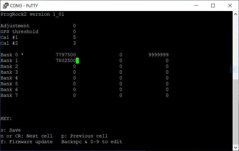
Note that you're specifying the frequency in Hertz. No decimal points at all. I typed one zero too many the first time and it was delivering 78.025 MHz instead of 7.8025. Didn't work at all.
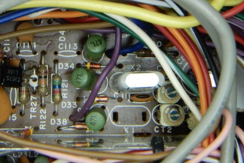
Two parts get removed to start. C113 and the X1 socket. Yeah, X2 will go away later. Just gets unplugged.
The power source was gonna be the sideband-select voltages that come from the mode selector. Didn't work. Here's the zener regulator that powers the mode-select section of the mode switch. Also powers the mike amplifier.
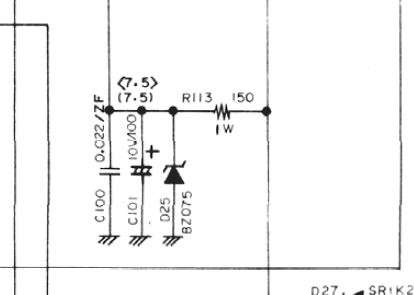
Turned out I needed more current. Removed D25 and R113 both. Whups! Failed to get pics of this. Those two parts are easy to find. They're perched alongside the very front edge of the pc board, between the two carrier crystals and the front board edge. They both get removed.
This solution probably needs to get refined, but this radio is a guinea pig. I soldered the tab of a 7808T regulator to the pcb ground under the whine choke. Serves as a demented heat sink. The output goes to the pad where D25 cathode was pulled.
The ProgRock module gets prepped with a NPN transistor to invert the LSB select line. Goes high when LSB is selected. The module needs a logic low input. . I used a 2N2222A. Just about any small NPN transistor will do this job.
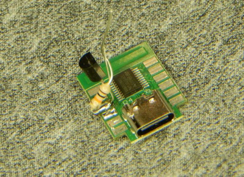
The resistor from base to emitter serves to make sure the transistor is fully off when not needed. Another 10k laps onto the base lead and goes to the LSB output from the mode selector.
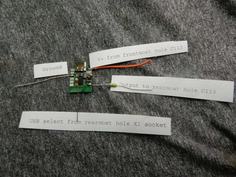
This what the module looks like ready to install. Power, ground, blocking cap on the output and one input wire to select LSB.
** edit ** Label got typed wrong. Should say LSB select from X1 socket. Oops **
Here's what holds it in place. Not your drug store foam tape. Just be sure to swab the target surface with alcohol beforehand.
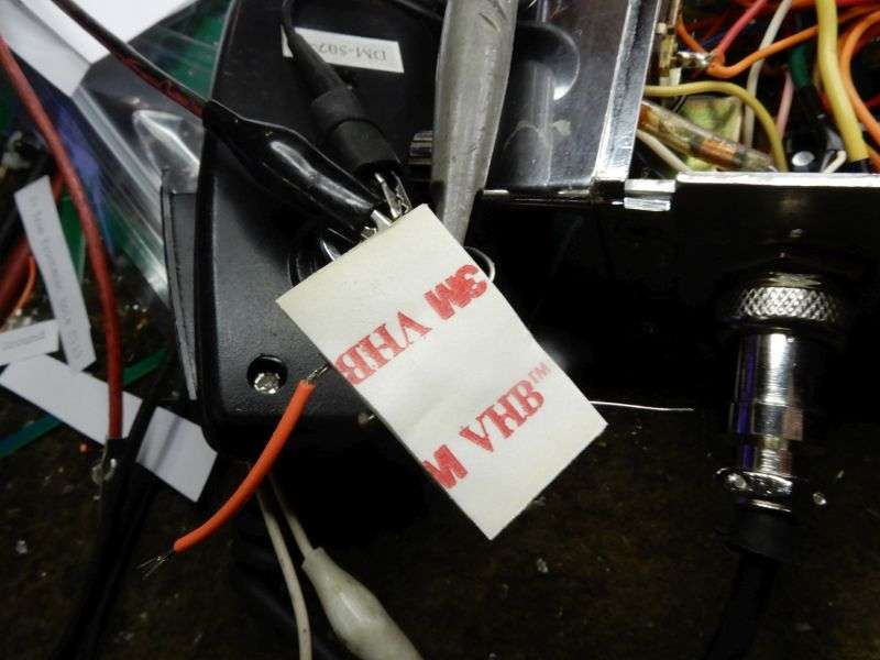
In place, connected.
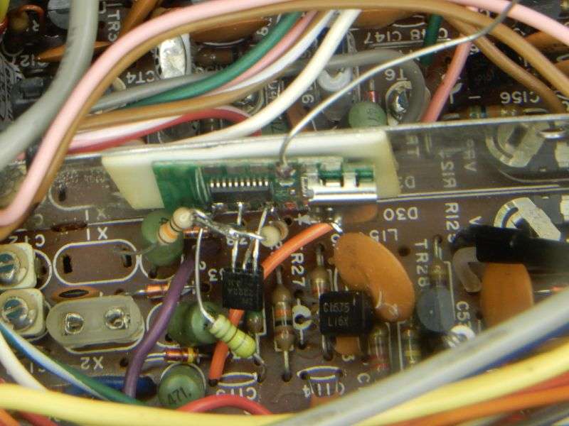
It was a bit lame at first. Almost enough drive level.
Here's the original carrier oscillator circuit.
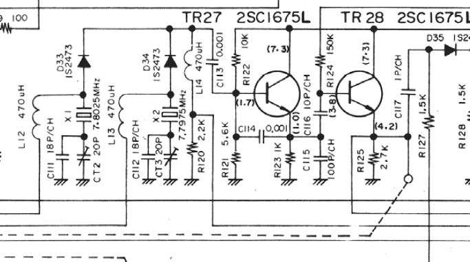
I removed C115. Lots of drive now. Wahoo!
Just didn't get a pic.
And yeah, I did solder the ground wire before I fired it up.
The high-school science-fair look of this mod tells me it needs a daughter board to host the added parts. Pretty sure this radio won't get used mobile, so all the 'flying' parts should not cause trouble. Wouldn't recommend using it in a dump truck.
No drafting any new pc boards today. Just the same, bad carrier crystals have caused me more than one headache. Gonna make this the remedy.
73
The X1 crystal supplies the 7.8025 MHz carrier for AM transmit and USB receive/transmit both. Now the arithmetic may sound wrong. The crystal filter's center frequency is 7.800 MHz. Placing the crystal frequency above it should generate a lower sideband, right? Not in this case. The radio's local oscillator is 7.8 MHz above the channel frequency. When the 7.xx MHz carrier frequency goes up, the difference between the two frequencies goes down. This causes the sideband to be inverted. A lower sideband going through the 7.8 MHz crystal filter becomes the upper sideband after we mix it with the 35 MHz PLL's output.
This radio uses the USB carrier crystal for the AM carrier, as well.
I have shown the ProgRock module from QRP labs here before, using it to replace the band crystals in Browning receivers. It can hold eight frequencies, selectable by three binary inputs. If you don't connect any of those three inputs, you get the default frequency. The setup requires a terminal program. The module emulates a serial COM port via the USB-C socket. We use PuTTY.
The module wakes up as COM3 on my system. Here's the setup screen you get by hitting enter after launching PuTTY.
Note that you're specifying the frequency in Hertz. No decimal points at all. I typed one zero too many the first time and it was delivering 78.025 MHz instead of 7.8025. Didn't work at all.
Two parts get removed to start. C113 and the X1 socket. Yeah, X2 will go away later. Just gets unplugged.
The power source was gonna be the sideband-select voltages that come from the mode selector. Didn't work. Here's the zener regulator that powers the mode-select section of the mode switch. Also powers the mike amplifier.
Turned out I needed more current. Removed D25 and R113 both. Whups! Failed to get pics of this. Those two parts are easy to find. They're perched alongside the very front edge of the pc board, between the two carrier crystals and the front board edge. They both get removed.
This solution probably needs to get refined, but this radio is a guinea pig. I soldered the tab of a 7808T regulator to the pcb ground under the whine choke. Serves as a demented heat sink. The output goes to the pad where D25 cathode was pulled.
The ProgRock module gets prepped with a NPN transistor to invert the LSB select line. Goes high when LSB is selected. The module needs a logic low input. . I used a 2N2222A. Just about any small NPN transistor will do this job.
The resistor from base to emitter serves to make sure the transistor is fully off when not needed. Another 10k laps onto the base lead and goes to the LSB output from the mode selector.
This what the module looks like ready to install. Power, ground, blocking cap on the output and one input wire to select LSB.
** edit ** Label got typed wrong. Should say LSB select from X1 socket. Oops **
Here's what holds it in place. Not your drug store foam tape. Just be sure to swab the target surface with alcohol beforehand.
In place, connected.
It was a bit lame at first. Almost enough drive level.
Here's the original carrier oscillator circuit.
I removed C115. Lots of drive now. Wahoo!
Just didn't get a pic.
And yeah, I did solder the ground wire before I fired it up.
The high-school science-fair look of this mod tells me it needs a daughter board to host the added parts. Pretty sure this radio won't get used mobile, so all the 'flying' parts should not cause trouble. Wouldn't recommend using it in a dump truck.
No drafting any new pc boards today. Just the same, bad carrier crystals have caused me more than one headache. Gonna make this the remedy.
73
Last edited:

