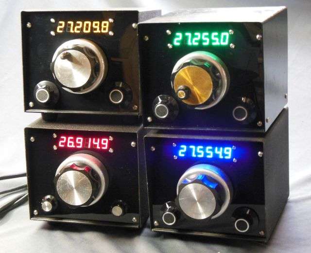
We've been using the six-digit PLJ-6LED version. They come with unshielded wires for both power and signal input.
You'll probably want to obtain a 7808T 3-terminal voltage regulator chip to power the counter from 8 Volts. Running it from the radio's main 13.8 Volts may overheat the counter's on-board regulator.
Tap off of the radio's test point TP1 for the counter's signal input. A 100 ohm resistor between TP1 and your counter input will prevent it from loading down the radio's internal signal level. If the signal lead isn't fairly short you may need to use shielded wire. The lower the capacitance per foot this wire has, the better.
I have no idea what's involved with setting a display offset. If it's the same as the 6-digit, no problem. Just haven't tried the 8-digit yet. Couldn't come up with a good reason.
Besides, putting them into an analog VFO would be a waste of the extra two digits, considering the way the frequency will drift.
73