• You can now help support WorldwideDX when you shop on Amazon at no additional cost to you! Simply follow this Shop on Amazon link first and a portion of any purchase is sent to WorldwideDX to help with site costs.
  • A Winner has been selected for the 2025 Radioddity Cyber Monday giveaway! Click Here to see who won!

Cobra 142GTL alignment challenge with unknown part installed

Lkaskel

Well-Known Member
I Support WorldwideDX.com!
Aug 4, 2017
521
433
73
61
Hi Everyone,
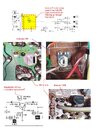
So, I am aligning this 142GLT and there is a VR installed in place of where T1 would be. I have been researching this and it seems that on the 140GTL T1 is installed but on the 142GLT it may not be. The VR is not labeled and there are no alignment details for it.

Any ideas?
 

If I recall, does that radio not have a modulation vr adjustment? I know there is a mod to add it at that missing transformer. A pic would be helpful too.

Edit, is it this guy?
IMG_20250927_144219044.jpg
If so, I think that's for modulation if my memory is correct. It's the madison and washington that deleted the vr and instead uses a resistor.
 
Last edited:
T1 is the "whine" choke, meant to reduce noise from a vehicle's alternator. The mobile 140GTL model has this, the base 142 radio does not. Sounds like your trimpot is VR12, the modulation meter calibrate pot. That's what the 142 schematic suggests, since the mobile 140 doesn't have a modulation meter.

Both 140 and 142 use the PC385 circuit board.

73
 
If I recall, does that radio not have a modulation vr adjustment? I know there is a mod to add it at that missing transformer. A pic would be helpful too.

Edit, is it this guy?
View attachment 74331
If so, I think that's for modulation if my memory is correct. It's the madison and washington that deleted the vr and instead uses a resistor.
That is the guy!!! My fault for not providing a pic. You are Da Man!!!
 
T1 is the "whine" choke, meant to reduce noise from a vehicle's alternator. The mobile 140GTL model has this, the base 142 radio does not. Sounds like your trimpot is VR12, the modulation meter calibrate pot. That's what the 142 schematic suggests, since the mobile 140 doesn't have a modulation meter.

Both 140 and 142 use the PC385 circuit board.

73
Man does that make sense!!! Thx so much Nomad as always!!!
 
OOPS!!! nomadradio, I was going through the alignment docs and on this radio they already have a mod meter adjustment (VR12) as you noted. This VR is a different, unlabeled one (see attached). Is it possible that it is for modulation? I make these board layouts to help me better see where thigs are and to reduce the amount of times I need to switch glasses from reading to magnifiers as the layout provided with the Sams manual is too hard to see otherwise :)
 

Attachments

Last edited:
Ok, so more of an update. This is interesting to see what manufactures do. The 142 board is a littte different that the 140. The 142 has holes in it for this VR that do not exist in the 140 (see the attachment). This VR is connectcted to TR33 (AMC) by a white wire (see attached). It takes the base of TR33 to ground. Maybe it is a mic gain setting?
 

Attachments

  • Cobra 140GTL-142GTL Unknown VR.jpg
    Cobra 140GTL-142GTL Unknown VR.jpg
    228 KB · Views: 9
That should be the modulation limiter, if my memory serves me. I will check it out when I get home. There is a mod to add that vr on similar board which lack it, and that is where it goes, to control modulation.
 
  • Like
Reactions: brandon7861
After looking through the schematic and comparing it to the board I see where that makes sense. One of the interesting things is that the VR and D70 are not shown on the schematic as well as this VR is not in the alignment guide. D70 is labeled on the board though. I figured it must be an update/service bulletin for that radio. Maybe this radio/board were manufactured after the initial release...
 
I have the original Sam's at home for it, I will check, but I believe modulation adjustment is included in it. I should be home in a few hours and will update then.
 
Cable guy is right, it's a modulation adjustment. It changes the base voltage on the AMC comparator (TR33). As the modulator (TR34) swings up and down, a fraction of that final supply (orange) is divided down at point A and compared with the bias voltage at point B. When point A drops 0.7v below point B, TR33 conducts and turns on TR31, which turns on TR32 shunting some of the audio to ground until it TR33 turns back off.

The reason for dividing down at point A is to protect the base-emitter of TR33 from reverse avalanche. By installing a diode in series with the VR replacing R105, the VR can never drop the base voltage below 0.7v which helps prevent negative peak clipping. If the base were allowed to be set to something as low as 0.4v, the (divided down at B) final supply (orange) would have to drop to -0.3v before any audio reduction takes place. Since the supply cannot go that low, the diode eliminates the chance of the wrong setting causing excessive clipping.
1759173446207.png
 
I was going through my folder at work just now and discovered my old galaxy AMC drawing that I never did anything with. The galaxy AMC works in the same way, and that one also had a diode (D92). It's easier to see with the rest of the circuit hidden. Probably not worth the bump, but maybe if enough people understand how that circuit works, they won't clip it.
AMC.png
 
  • Like
Reactions: Cable Guy and Tech5

dxChat
Help Users
  • No one is chatting at the moment.