I realize I jumped ahead of myself for I wanted to point out something that you had asked earlier - that I needed to address as an upgrade - forgot to mention that...
A secondary event also is taking place.
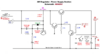
The output power of this circuit to maintain the "center point" has to be able to sense the output as a measure of power and means to restore order by locating - stabilizing to - and working with - the output power of the main amplifier in the Darlington in a way to provide Feedback and error correction control to restore DC bias and the "Center point" and also sense and respond to the Audio Signal to correct itself from too much drive or if DC Bias rises and Falls below a set level of time predetermined by a set of filters, one being the sense lead of the output, the other from a series pass circuit used as a Gain cell - between these two filters a level of power is detected, and used - applied back into the Darlington pair - as a form of control, or REGULATION.
I mention filters because one filter is taking in power by tapping the output back into and to be used by the other filter as a means to control the Audios Envelope - or bandwidth - as a process of regulation.
What they do in the 142 and 2000/148 lines use a AMC/ALC together at the mic amp to control the VOLUME of audio - doesn't do much for the development and center point for recovery does it?
That's where I jumped ahead...
Your typical Cobra 2000/148/142 AM output - is not truly regulated, more like USES regulated voltage as that bias set point for Carrier - the only feedback being the AMC/ALC stuff using R166 and R165 as a divider combo to sense a pre-determined mid-point and then Limit the modulation using this method.
I jumped ahead because other radios now use a Sense circuit in AM Regulator section - using the output of the regulator as the means to set and regulate itself. Not depending and or dependent on the 8 volt regulation signal sent to the TR42 to be mixed with Audio and amplified to swing current at TR41. It's still there to set mid point, But the
LEVEL of audio drive, it's gain is set to a specific level - which; in the Case of the 2000/148/142 - it is not - you can throw several watts of audio to swing the current output at TR41 using the input at TR42 to do this.
Just review this thread...
https://www.worldwidedx.com/threads/over-130-modulation.163831/page-2#post-457911
Speaks volumes more about it than I can...
The part about the 220 ohm resistor then becomes more clear, as it' really is not needed, but it is there to offset a linearity issue that TR42/TR41 have regarding dissipation and clipping - they felt at the time it was more important to pre-set a power level across a known load, across the Pass transistor as a method to keep the Driver and Final more Forward Biased - then they found the Regulation method used and is common nowadays - it is not used in the 2000/148/142 series.
Compare this schematic to the one about 4 posts ago...

But this concept of self-centering AM Regulation that was incorporated into the 146GTL - was their last one of their last truly USA designed and FCC type accepted radios - none of their other radios produced since then ever used the AM Regulation design like the 146GTL - the 148/2000 series is their last effort at what the Link above describes.
Only Galaxy and RCI have taken the AM Regulator section a few revisions and upgrades since then...
EDITs:
Updated Graphic Blandishment


.JPG")
